HD Turret and Bullet Camera User Manual User Manual Thank you for purchasing our product. If there are any questions, or requests, do not hesitate to contact the dealer.
Regulatory Information FCC Information Please take attention that changes or modification not expressly approved by the party responsible for compliance could void the user’s authority to operate the equipment. FCC compliance: This equipment has been tested and found to comply with the limits for a Class A digital device, pursuant to part 15 of the FCC Rules. These limits are designed to provide reasonable protection against harmful interference when the equipment is operated in a commercial environment.
Safety Instruction These instructions are intended to ensure that user can use the product correctly to avoid danger or property loss. The precaution measure is divided into “Warnings” and “Cautions”. Warnings: Serious injury or death may occur if any of the warnings are neglected. Cautions: Injury or equipment damage may occur if any of the cautions are neglected. Warnings Follow these safeguards to prevent serious injury or death.
To avoid heat accumulation, good ventilation is required for the operating environment. Keep the camera away from liquid while in use for non-water-proof device. While in delivery, the camera shall be packed in its original packing, or packing of the same texture. Mark Description Table 0-1 Mark Description Mark Description DC Voltage 1 Introduction 1.
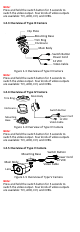
Note: Press and hold the switch button for 5 seconds to switch the video output. Four kinds of video outputs are available: TVI, AHD, CVI, and CVBS. 1.2.3 Overview of Type III Camera Clip Plate Mounting Base Trim Ring Enclosure Main Body IN DC12V Switch Button Power Cord 12 VDC Video Cable Figure 1-3 Overview of Type III Camera Note: Press and hold the switch button for 5 seconds to switch the video output. Four kinds of video outputs are available: TVI, AHD, CVI, and CVBS. 1.2.
1.2.6 Overview of Type VI Camera Mounting Base Switch Button IN DC12V Main Body Lens Power Cord 12 VDC Video Cable Figure 1-6 Overview of Type VI Camera Note: Press and hold the switch button for 5 seconds to switch the video output. Four kinds of video outputs are available: TVI, AHD, CVI, and CVBS. 2 Installation Before you start: Make sure that the device in the package is in good condition and all the assembly parts are included.
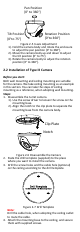
4. Drill the screw holes, and the cable hole (optional) on the ceiling according to the drill template. Cable Hole Screw Hole Side Opening Figure 2-2 Drill Template Note: Drill the cable hole, when adopting the ceiling outlet to route the cable. 5. Attach the mounting base to the ceiling, and secure them with supplied screws. Type I Camera Type II Camera Figure 2-3 Attach the Mounting Base to the Ceiling Note: The supplied screw package contains self-tapping screws, and expansion bolts.
Pan Position [0° to 360°] Tilt Position [0°to 75°] Rotation Position [0°to 360°] Figure 2-5 3-axis Adjustment 1). Hold the camera body and rotate the enclosure to adjust the pan position [0° to 360°]. 2). Move the camera body up and down to adjust the tilt position [0° to 75°]. 3). Rotate the camera body to adjust the rotation position [0° to 360°]. 2.2 Installation of Type III Camera Before you start: Both wall mounting and ceiling mounting are suitable for the camera.
Figure 2-8 Attach the Mounting Base to the Ceiling Note: The supplied screw package contains self-tapping screws, and expansion bolts. For cement ceiling, expansion bolts are required to fix the camera. For wooden ceiling, self-tapping screws are required. 5. Route the cables through the cable hole, or the side opening. 6. Combine the camera body with the mounting base. 1). Put the camera body in the mounting base. 2). Align the notch to the clip plate, and rotate the enclosure a little bit. 3).
Before you start: Both wall mounting and ceiling mounting are suitable for the camera. We take ceiling mounting as an example in this section. You can take the steps of ceiling mounting as a reference, when adopting wall mounting. Steps: 1. Disassemble the turret camera by rotating the trim ring anticlockwise to get the trim ring out of the camera as shown in the figure below. Figure 2-11 Get the Trim Ring out 2. Paste the drill template (supplied) to the place where you want to install the camera.
Figure 2-14 Put the Trim Ring Back and Tighten It 6. Connect the corresponding cables, such as power cord, and video cable. 7. Power on the camera to check whether the image on the monitor is gotten from the optimum angle. If not, adjust the camera according to the figure below to get an optimum angle. 1 Rotate Clockwise 2 Pan Position [0° to 360°] Rotation Position [0° to 360°] Tilt Position [0° to 75°] Figure 2-15 3-axis Adjustment 2.
Note: Drill the cable hole, when adopting the ceiling outlet to route the cable. 3. Attach the bracket to the ceiling and secure the camera with supplied screws. Figure 2-17 Fix the Camera to the Ceiling Note: The supplied screw package contains self-tapping screws, and expansion bolts. For cement ceiling, expansion bolts are required to fix the camera. For wooden ceiling, self-tapping screws are required. 4. Route the cables through the cable hole, or the side opening. 5.
TVI DVR Camera Monitor Figure 3-1 Connection 2. Power on the analog camera, TVI DVR, and the monitor to view the image on the monitor. 3. Click PTZ Control to enter the PTZ Control interface. 4. Call the camera menu by clicking button, or click Iris+.
3.2 EXPOSURE Exposure describes the brightness-related parameters, which you can set the EXPOSURE MODE as GLOBAL, BLC, or DWDR. GLOBAL GLOBAL refers to the normal exposure mode which performs exposure according to the whole image brightness. BLC (Backlight Compensation) BLC (Backlight Compensation) compensates light for the front object to make it clear, but this may cause the over-exposure of the background, where the light is strong.
DAY/NIGHT MODE IR LIGHT SMART IR D à N THRESHOLD N à D THRESHOLD BACK EXIT SAVE & EXIT AUTO ON 2 2 7 Figure 3-4 AUTO IR LIGHT You can turn on/off the IR LIGHT to meet the requirements of different circumstances. SMART IR The SMART IR function is used to adjust the light to its most suitable intensity, and prevent the image from over exposure. The SMART IR value can be adjusted from 0 to 3. The higher the value is, the more obvious effects are.
SHARPNESS Sharpness determines the amount of detail an imaging system can reproduce. You can set the SHARPNESS value from 1 to 9. SATURATION Adjust this feature to change the saturation of the color. The value ranges from 1 to 9. DNR (Digital Noise Reduction) The DNR function can decrease the noise effect, especially when capturing moving images in poor light conditions and delivering more accurate and sharp image. You can set the DNR as HIGH, MEDIUM, or LOW.