User Manual Model name:FOREVER Brand name:MYCOM
AMENDMENT HISTORY S/N Rev Description of Change 1 1.
Contents 1. Objective ..............................................................................................................................................4 2. Scope ....................................................................................................................................................4 3. Definition for terms ..............................................................................................................................4 4. Responsibility .................
1. Objective This document outlines the service manual. 2. Scope 1.Use for radio analyzing in factory. 2.Use for radio analyzing in customer service. 3. Definition for terms Nil 4. Responsibility Nil 5.
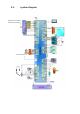
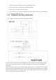
.1. system diagram 26M GSM 850:824.2-848.8MHz 1900:1850.2-1909.
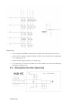
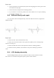
5.2. Vibration issue: The vibrator circuit is simple, one point connected to VBAT and the other to VIB_CTRL. VBAT voltage is approximately equal to battery voltage, and VIB_CTRL voltage outputs from the core chip and is controlled by the software. When vibration enabled, the differential voltage of the vibrator is close to 3.0 v, when vibration disabled, the differential voltage is close to 0 v. Repair steps: 1. Check whether the Vibrator is damaged and the soldering is well or not; 2.
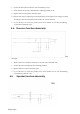
Repair steps: 1. Check if keypad and DOME are damaged, the assembly OK ,and foreign matter exist, etc; 2. Check if the surrounding components (mainly varistors) on the main board are damaged and have soldering issues, etc; 3. Replace with new keypad or side key, and verify again; 4. If you still have not found the problem, then check whether the U1 chip has soldering or performance problems or not. 5.4.
1. Check if the microphone and lead is well ,and soldering is well ; 2. Check whether the relevant components have soldering problems or not; 3. Replace with new microphone, and verify again; 4. Enter the call state (or engineering test mode),measuring if microphone’s bias voltage is normal: the voltage is when the microphone works about 1.8V, and 0V when off; 5. If you still have not found the problem, then check whether the U1 chip has soldering or performance problems or not. 5.5.
1. Check if the speaker and the lead are well, and soldering is well; 2. Check if the relevant components have soldering problems; 3. Replace with new speaker, and verify again; 4. If you still have not found the problem, then check whether the U1 chip has soldering or performance problems or not. 5.7. Earphone function abnormity F9 earphone is sharing one interface with headphone JACK.
Repair steps: 1. Check if the headset can be detected by the phone after being plugged. If cannot, replace with a new headset and verify again; 2. Check if the relevant components have soldering problems; 3. If you still have not found the problem, then check whether the U1 chip has soldering or performance problems or not. 5.8. SIM card theory and repair F9 has a built-in dual-card management chip, and has two SIM card connectors, supports dual SIM dual standby. Repair steps: 1.
Repair steps: 1. Check if the LCD is damaged, and FPC has soldering problems; 2. Check if t h e relevant components h ave soldering problems; 3. Replace with new LCD, and verify again; 4. If still failed to find out problems, check whether U1 chip has soldering or performance problems. 5.10. Camera function abnomity F9, configured with a 0.3 million pixels main camera, the data and control lines which connect to the main chip’s camera interface directly.
Repair steps: 1. Check if the camera has quality problem, and FPC has assembly problem; 2. Check if the camera’s power supply voltage is normal, a n d components around CAM have soldering problems; 3. Replace with new camera, and verify again. 4. If still failed to find out problems, check whether U1 chip has soldering or performance problems.
Repair steps: 1. Check if the T card connector’s COM1 has quality problem, metal contact points abnormal; 2. Check if T card connector and components around have soldering problems; 3. If still failed to find out problems, check whether U1 chip has soldering or performance problems. b) Charging function abnormity Repair steps: 1. Check if the USB J1 socket pins rust or have soldering problems; 2.
Annex Baseband functions test under the engineering mode 1. Power on the phone to the idle screen, and input "*#80# " to enter the "test menu"; 2. Select “Keypad” function test, and the screen will prompt the current testing key, then press the key accordingly until all the keys are tested, and exit automatically. If a certain key doesn’t work or press a wrong key, then the screen will show the key that will test, and exit automatically in 5 seconds without action. 2.
FCC FCC RF Exposure Information and Statement The SAR limit of USA (FCC) is 1.6 W/kg averaged over on one gram of tissue. Device types: FOREVER (FCCID: 2AB7A-2015) has also been tested against this SAR limit. The highest SAR value reported under this standard during product certification for use at the ear is 0.250 W/kg and when properly worn on the body is 0.593 W/kg. This device was tested for typical body-worn operations with the back of the handset kept 1.0 cm from the body.