Manual 3.
Important Safety Instructions Before connecting, read instructions • • • • • • • • • • • • • • • • • • • • • • • • • • Read all of these instructions! Save these instructions for later use! Follow all warnings and instructions marked on the product! Do not use this product near water, i.e. bathtub, sink, swimming pool, wet basement, etc. Do not place this product on an unstable cart, stand or table.
Conseils de Securite Importants! Priere de lire avant l'emploi et a conserver pour utilisation ulterieure! • L'appareil a été conçu par HK AUDIO® selon la norme IEC 60065 et a quitté l'entreprise dans un état irréprochable. Afin de conserver cet état et d'assurer un fonctionnement sans danger de l'appareil nous conseillons à l'utilisateur la lecture des indications de sécurité contenues dans le mode d'emploi. L'appareil est conforme à la classification I (mise à terre de protection).
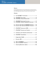
Manual COHEDRA® & COHEDRA® Compact Preface This manual is addressed to all technicians who are responsible for setting up, operating and maintaining the HK Audio® Cohedra™ Compact system. In addition, we would like to explain in detail the principles and functions of HK Audio® Cohedra™ technology to all interested planning and installation engineers. Content A Die COHEDRA® Technology .....................................5 B COHEDRA® Enclosures ...........................................
® The COHEDRA Technology 1 Line Array Approaches in Recent Years ............ 6 2 2.1 2.2 2.3 Development Objectives ................................ 7 High Frequency Range .................................... 7 Middle Frequency Range .................................. 7 Low Frequency Range ....................................... 7 3 3.1 3.2 3.3 Emphasized Radiation Technology™ ............... 7 The High Frequency Wave Front .......................8 Midrange.........................................
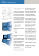
Manual COHEDRA® & COHEDRA® Compact 1 Line Array Approaches in Recent Years Line arrays are a fixture on the contemporary sound reinforcement scene. The design principle has its origins in the stacks of cone loudspeakers that were popular in the '70s. Some 20 years later, the coherent wave front's ingress into the high frequency range through waveguides and acoustical mirrors ushered in a second generation of line arrays.
COHEDRA® Technology 2 Development Objectives The tweeter should radiate coherent waves throughout its frequency range. In addition, the phase position should be fine-tuned and tweaked to harmonize with the midrange woofer to afford the highest possible fidelity and natural response. In order to ensure uniform dispersion of sound, the driver should channel into a constant directivity horn that is free of undesirable diffractive effects and does not adulterate the sonic image. 2.
Manual COHEDRA® & COHEDRA® Compact 3.1 The High Frequency Wave Front A specially developed and patented acoustic lens serves to curve the wave front. It transforms the spherical wave emitted by the high frequency driver into an inward curving wave front. To shape a curved wave front, the sound wave's inner components are re-channeled into a bisected, centrically symmetrical array.
COHEDRA® Technology 3.2 Midrange A special speaker cover is located in front of the two 8" midrange speakers. Designed to shape the horn contour with CD characteristic in front of the acoustic lens, it is free of undesirable diffractive effects and does not adulterate the sonic image. It does not constrict the HF range and ensures greater stability in the face of gusts of wind. The sound of the 8" speakers emanates through slots on the top and bottom of this cover.
Manual COHEDRA® & COHEDRA® Compact Chapter B The COHEDRA® Loudspeakers 1 1.1 1.2 1.3 COHEDRA® Loudspeakers ..................... 11 CDR 208 S and CDR 208 T Mid/High Enclosures................................................11 CDR 210 Sub Subwoofer ......................... 12 CDR 210 F Sub Subwoofer .......................13 Index of Figures: Fig. 1: Cohedra CDR 208 T..................................11 Fig. 2: Cohedra CDR 208 S..................................11 Fig. 3: Cohedra CDR 210 Sub ............
The COHEDRA® Loudspeakers 1 COHEDRA® Loudspeakers Design and Construction of the Mid/High Enclosures Two types of housings are available, the purpose of the different design being to optimize the typical "J" form of mid/high arrays. The CDR 208 S is housed in a straight rather than slanted cabinet. The CDR 208 T (T is short of trapezoidal) enclosure's top and bottom are slanted at 4.5° angles, a design that enables the configuration of sharply curving down-fills.
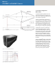
Manual COHEDRA® & COHEDRA® Compact Figure 3: Cohedra CDR 210 Sub 1.2 CDR 210 Sub Subwoofer Design and Construction of the Subwoofer The CDR 210 Sub enclosure is made of 19 mm, 13-ply birch plywood and coated with water-repellent, black acrylic enamel. The baffle board cover consists of a metal grille. The CDR 210 Sub weighs 33 kg. It is 110 cm wide, 32 high and 40 cm deep. Two slot grips have been routed into the side panels for easy transport and set-up.
The COHEDRA® Loudspeakers 13 B Figure 4: Cohedra CDR 210 F Sub 1.3 The CDR 210 F Sub Subwoofer Design and Construction of the Subwoofer The CDR 210 F Sub's enclosure is made of 19 mm, 13-ply birch plywood and coated with water-repellent, black acrylic enamel. The baffle board cover consists of a metal grille. The CDR 210 F Sub weighs 40 kg. It is 65.5 cm wide, 48 cm high and 60 cm deep. Two slot grips have been routed into the side panels for easy transport and set-up.
Manual COHEDRA® & COHEDRA® Compact Chapter B 1 The COHEDRA® Compact Loudspeakers 1 COHEDRA® Compact Enclosures . . . . . . . . 15 1.1 The CDR 108 C Mid/High Unit 15 1.
The COHEDRA® Compact Loudspeakers 1 COHEDRA® Compact Enclosures 1.1 The CDR 108 C Mid/High Unit Serving to fly the mid/high units are fully integrated rigging attachments comprising four quick-release pins and three rigging connectors, two mounted on the sides and one in the rear. Electrical and Acoustical Data The CDR 108 C enclosure is loaded with an 8" cone chassis speaker and two 1" B&C high frequency drivers with a front-mounted acoustical lens in a CD horn configuration.
Manual COHEDRA® & COHEDRA® Compact 1.2 The Subwoofer CDR 210 C Design and Construction of the Subwoofer Made of 19 mm, 13-ply birch plywood, the CDR 210 C enclosure is coated with water-repellent, black acrylic enamel. The baffle board cover consists of a metal grille. The CDR 210 C weighs 48 kg. It is 55 cm wide, 60 high and 63 cm deep. Two slot grips have been routed into the top, bottom and back panels for easy transport and set-up.
Chapter C COHEDRA® Transport Solution Index of Figures: Fig. 1: COHEDRA® Mid/ High-Case ................... 18 Fig. 2: COHEDRA® Subwoofer-Dolly .................. 18 Fig. 3: 16 Mid/ High-Cabinets and 16 Subwoofers ................................... 19 Fig. 4: 24 Mid/ High-Cabinets and 24 Subwoofers ................................... 19 Fig. 5: 32 Mid/ High-Cabinets and 32 Subwoofers ................................... 19 Fig. 6: 48 Mid/ High-Cabinets and 48 Subwoofers ................................
Manual COHEDRA® & COHEDRA® Compact The COHEDRA® Transport Solution 1.1 Mid/High Enclosures A specially designed case serves to transport the COHEDRA® CDR 208 S, CDR 208 T mid/high and the CDR 210 F Sub enclosures. The floor of the mid/high enclosure case is adjustable to 0° and 4.5°. This enables you to configure the S and T model housing as desired without having to disassemble clusters consisting of up to four mid/ high enclosures for transport. 1.
COHEDRA® Transport Solution 19 1.4 COHEDRA® Truck Space The dimensions of COHEDRA® cases, racks and dollies were selected specifically to make the most of available truck space. The diagrams below offer suggestions on how to load different COHEDRA® systems into a truck with a width of 240 cm.
Manual COHEDRA® & COHEDRA® Compact Chapter C 1 COHEDRA® Compact Transport Solution 1 COHEDRA® Compact Transport Solution. . . .21 1.1 CDR 108 C Mid/High Case . . . . . . . . . . . . . . . 21 1.2 Dimensions and Weights . . . . . . . . . . . . . . . . . 21 Index of Figures: Fig. 1: COHEDRA® Compact Mid/High Case. . . 21 Fig. 2: 16 Mid/High enclosures and 8 Subwoofers. . . . . . . . . . . . . . . . . . . . . . .
COHEDRA® Compact Transport Solution 1 COHEDRA® Compact Transport Solution 1.1 CDR 108 C Mid/ High Case A specially designed case serves to transport COHEDRA® Compact CDR 108 C mid/high enclosures. One case accommodates four CDR 108 Cs and a standard rigging frame each. 1.2 Dimensions and Weights PR 8 (lying): Width: 60 cm/ 23 5/8" Height: 38.5 cm/ 15 1/8" Depth (standing on casters): 95 cm/ 37 3/8" Weight: approx. 65 kg/ 143.3 lbs.
Manual COHEDRA® & COHEDRA® Compact Chapter D Rigging & Curving the COHEDRA® System Rigging and Curving Mid/high Cabinets ............... 23 1 Use 26 1.1 Intended Use .................................................. 23 1.2 Unintended Use .............................................. 23 2 Warranty and Liability .................................... 23 3 Important Notes on Safety ............................. 23 3.1 Responsibilities of the Operator ..................... 23 3.
Rigging and Curving COHEDRA® System Rigging and Curving COHEDRA® Mid/high Cabinets Please read these instructions carefully before you begin setting up the system! 1 Use 1.1 Intended Use Any use other than specified is unintended. The manufacturer shall not be liable for damages resulting from unintended use. 1.2 Unintended Use Improper use of rigging frames and incorrect handling of this load-carrying equipment can pose a serious danger.
Manual COHEDRA® & COHEDRA® Compact 3.2 Storage, Maintenance, Inspection and Repair of COHEDRA® Rigging Hardware Warning: Flying more than 24 enclosures in a stacked array from the standard rigging frame voids the safety standards authority TÜV's certification! Storage, temporary and long-term When not in use store the truss indoors in a safe place where it cannot be tipped over and is protect from exposure to the elements. Refer to table 1 to determine flown loads.
Rigging and Curving COHEDRA® System 3.5 Maximum Number of Flown COHEDRA® CDR 210 F Subwoofers 3.7 Pick Points for Flying COHEDRA® Mid/high Enclosures The standard rigging frame can fly up to 20 vertically arrayed CDR 210 F Subs. If you are using a combination of CDR 208 S/T cabinets and CDR 210 F Sub bins on one rigging frame, calculate the total load using both tables. Ensure the rigging frame's maximum permissible load is never exceeded.
Manual COHEDRA® & COHEDRA® Compact 4 Components of the COHEDRA® Rigging Hardware Figure 4: Shackles for attaching motors, straps Figure 5: Bottom rigging frame Figure 1: 12 COHEDRA® mid/high enclosures Figure 6: Lashing strap for curving the array Figure 2: Mid/high enclosure with integrated flight attachments Figure 3: Top rigging frame Figure 7: Quick-release pin COHEDRA® rigging hardware consists of the following parts: • a top rigging frame with three shackles for attaching motors, lashing strap
Rigging and Curving COHEDRA® System 5 Determining the Curving Angle between Two COHEDRA® Mid/ High Enclosures The curving angle between two enclosures is set by simply adjusting one pin. One person can easily carry out the entire process of curving cabinets. The rigging equipment is designed so that the curving angle can still be adjusted when COHEDRA® mid/high arrays are flown (see Fig. 9).
Manual COHEDRA® & COHEDRA® Compact 7 Mounting the Top Rigging Frame Figure 11: Open case with four mid/high range enclosures Figure 12 d Figure 12 a Figure 12 e Figure 12 b Figure 12 f Figure 12 c Figure 12 g The tasks described below require two people. Remove all three quick-release pins from their receptacles on the top rigging frame and the top pin on the back of the top mid/high range enclosure (preferably CDR 208 S). Set the top rigging frame on the topmost enclosure.
Rigging and Curving COHEDRA® System 29 Now connect the back of the top rigging frame to the enclosure (see Fig. 13). Important note: For this purpose, the pin must be inserted through the slot and into the 0 °s position! Always on the CDR 208 S. See Figure 10. Attach to the top rigging frame the shackle destined to accept the motor hook (see Fig. 14). Your choice of pick point depends on how sharply you aim to curve the COHEDRA® mid/high array.
Manual COHEDRA® & COHEDRA® Compact 8 Mounting Additional COHEDRA® Mid/High Enclosures Hoist the cabinets to a height that allows you to roll a second case with four mid/high range enclosures under the array. Remove both front pins from the lowest flown enclosure and the bottom pin on the back (see Fig. 16). Tip: Insert the front pins into the carrying handles on the sides of the mid/high range enclosure. This ensures that they are out of the way when the bottom enclosures are placed in position.
Rigging and Curving COHEDRA® System 9 Attaching the Bottom Rigging Frame and Raising the Mid/high Array Once all COHEDRA® mid/high enclosures have been assembled in the desired array, you must attach the bottom rigging frame to the lowest enclosure. To do this, remove all three pins from the lowest enclosure. First attach the front of the bottom rigging frame and secure it using the pins, and then insert the rear pin.
Manual COHEDRA® & COHEDRA® Compact 10 Ground Stacking 10.2 Ground Stacking with the Rigging Frame 10.1 Ground Stacking with the Stack Frame This option is recommended for smaller (four mid/ high units) configurations in venues that do not allow enclosures to be flown, or when you want to cover galleries, terraces or balconies. The stack frame was developed especially for ground-stacking CDR 208 S/T and CDR 210 F Sub enclosures.
Rigging and Curving COHEDRA® System 33 11.2 Bass Cluster/ Stacking In the classic right/left stacked configuration, one half of the bass bins is arrayed to the right of the stage, the other to the left. Advantages: The stacked bass bin configuration depicted above is a conventional and widely accepted option. It is very easy to deal with (short cables and walking distances).
Manual COHEDRA® & COHEDRA® Compact 12. Flying CDR 210 F Subs 13. The SL 218 as a Bass Supplement 12.1 As an Independent Bass Array Using A Second Rigging Frame Up to 20 CDR 210 F enclosures may be flown in a stacked array using the standard rigging frame. Please also read and heed the safety rules discussed in chapter D of the manual.
Rigging and Curving COHEDRA® System manual to learn more about how to do this. Before you can procedure further, you must first connect to the amp racks the DFCs' remote line and all of the system's audio cords. 14.3 Checking Individual Mid/ High Cabinets The best method of checking cabinets is to play a familiar song on a CD, routing the signal into the mixer and out via the master channel. Set the master level to a low-to-medium setting. • Turn up the channel's gain knob.
Manual COHEDRA® & COHEDRA® Compact Chapter D 1 Rigging & Curving the COHEDRA® Compact System 1 Use 1.1 Intended Use.................................................. 37 1.2 Unintended Use ............................................. 37 2 2.1 2.2 2.3 2.4 2.5 2.6 2.7 2.8 2.9 Warranty and Liability.................................... 37 Important Notes on Safety ............................. 37 Responsibilities of the Operator ....................
Rigging and Curving COHEDRA® Compact System Rigging COHEDRA® Compact Systems Please read these instructions carefully before you begin setting up the system! 1 Use 1.1 Intended Use Specifications for intended use include the following: • When rigging enclosures, make sure that the load is centered directly under the suspension point on the rigging frame. • The rigging frame may be tilted (not to be confused with curved!) no more than 10% (6°).
Manual COHEDRA® & COHEDRA® Compact 2.1 Responsibilities of the Operator As the operator, you are obligated to allow only those persons to work with rigging frames who are • 16 years of age or older, • physically and mentally able, familiar with the basic rules of industrial safety and accident prevention, and trained in the handling of rigging frames. Be sure to regularly review and confirm personnel’s working safety awareness.
Rigging and Curving COHEDRA® Compact System 2.5 Maximum Permissible Number of Flown COHEDRA® Compact CDR 210 C Subwoofers • No more than six CDR 210 C subwoofers may be flown in stacked array with the standard rigging frame. Warning: Flying more than six subwoofers in stacked array voids the safety standards authority TÜV’s certification! CDR 210 C subwoofers and CDR 108 C mid/high units may also be flown together on one rigging frame. Refer to table 2 to determine flown loads.
Manual COHEDRA® & COHEDRA® Compact Figure 5: COHEDRA® Compact lightweight rigging 3 Components and Applications of COHEDRA® Compact Rigging Hardware frame Figure 6: Optional quick-release pins for flying up to six CDR 108 C enclosures Figure 7: Shackles for attaching motors, straps Figure 2: 16 COHEDRA® – CDR 108 C COHEDRA® Compact rigging hardware consists of the following parts: • a standard rigging frame with two shackles for attaching motors, lashing straps or chain hoists.
Rigging and Curving COHEDRA® Compact System Setting Up a Horizontal Array You can configure up to three CDR 108 C enclosures in a horizontal array using quick-release pins. Connect three CDR 108 C enclosures and set the splay between the enclosures for fixed mode and in accordance with the given requirements. To learn more about this, read the chapter Determining the Splay Between Two CDR 108 C Enclosures.
Manual COHEDRA® & COHEDRA® Compact Note: Depending on application, you may not be able to select a pick point with a shackle. In this case, use two shackles and a suitable O ring as shown in Figure 14. Check all pins on the top rigging frame to ensure they are firmly seated and attach the motor to the shackle.
Rigging and Curving COHEDRA® Compact System Hoist the COHEDRA® Compact array with the eight enclosures just high enough to remove it from the case. Insert the pins on the back of the bottom four enclosures’ Set Angle holes to achieve the desired curving angle. Connect the remaining speaker cords. Repeat the above procedure to configure even more CDR 108 enclosures in a flown stacked array.
Manual COHEDRA® & COHEDRA® Compact Figure 21: CDR 210 C Rigging Set 5 Flying CDR 210 C Subwoofers 6 Configuring CDR 210 C Subwoofers in Clusters 5.1 Components CDR 210 C enclosures have been optimized for setting up clusters comprising four subwoofers. When configuring a cluster, set up the bins so that the bass reflex apertures point toward each other. This ensures the various subwoofers’ low-frequency signals couple for maximum sonic effect.
Rigging and Curving COHEDRA® Compact System 7 Ground-stacking 7.2 With CDR 210 C Subwoofers This option is recommended for smaller venues, for example, in which enclosures cannot be flown, or when you want to align the array to cover galleries, terraces or balconies. You can configure stacks with or without CDR 210 C subwoofers, as the given application may require. In both cases, you must use a standard rigging frame as the base for the mid/high cabinets.
Manual COHEDRA® & COHEDRA® Compact 8 Operating the System We recommend the following procedure to help prevent errors and troubleshoot problems quickly. The adverse effect of a mid/high cabinet dropping out or an incorrect connection can seriously degrade a line array’s performance! 8.1 Connecting Speaker Cords Always ensure cables are laid out clearly and orderly! You should be able to attribute enclosures to their connected power amp channel and/or amp rack at any time.
Rigging and Curving COHEDRA® Compact System 47 9 Tearing Down and Transporting the System As the somewhat clichéd but certainly true adage goes: To disassemble the system, proceed in the reverse order of assembly. D1 These tips should make the task of tearing down the mid/high array easier: 1 Lower the array until the bottom of the mid/high case fits under it. 2 Engage the motor or chain hoist to relax the tension on the strap that is curving the array.
Manual COHEDRA® & COHEDRA® Compact Chapter E Setup with Caps 1 1.1 1.2 1.3 Introduction ....................................................49 Acoustic Simulation for Line Arrays ............... 49 Remarks on SPL Calculation in CAPS ...............50 The Purpose of CAPS ....................................... 51 2 2.1 2.2 2.3 Installing and Launching CAPS ........................51 System Requirements ..................................... 51 Installation..................................................
COHEDRA® Setups with CAPS 1 Introduction CAPS (Cohedra Acoustic Prediction Software) providesthe tools and support you need to plan and configure HK AUDIO® COHEDRA® line arrays. To this end, it features many useful functions and handlesintuitively. Despite its ease of use, please take thetime to read this manual and learn to make themost of all its features so you can achieve the best possible audio results every time you deploy a COHEDRA® system. 1.
Manual COHEDRA® & COHEDRA® Compact Acoustic simulation for COHEDRA® CAPS Runs on all Win xx platforms 2D cut model Direct sound calculation Application: Day-to-day use when touring EASE DLL Dynamic Link Library plug-in for EASE 4.0 3D volume model Calculation of all simulations: direct sound, ALCons, RaSTI, ray tracing, auralization Application: Precision simulations for fixed installations Data import 1.
COHEDRA® Setups with CAPS 1.3 The Purpose of CAPS Note! Bear in mind that precisely measuring a room's geometrical specs (particularly the audience areas) and carefully planning the COHEDRA® configuration using CAPS will always take less time than determining the best possible configuration by trial and error. Oftentimes, DXF data – or at least scale diagrams of halls – are available on venues' websites. These sources can provide all the information required for a simulation.
Manual COHEDRA® & COHEDRA® Compact Figure 3: Dialog "Select System" Figure 4: File menu 3 Launching CAPS 3.2 Tools Menu During installation, the Installation Assistant creates links called CAPS on the desktop of your computer and in START > PROGRAMS > HK AUDIO > CAPS. Click these links to start CAPS. After launching the program, the user interface appears on your screen with a menu bar and the default Location panel.
COHEDRA® Setups with CAPS 53 3.4 Help Menu Use the menu option About to open a window providing general information on CAPS, the version number, and your computer system. 3.5 Location Panel Open the Location panel to begin creating a new project. In box 1, enter the room measurements (depth and height), the FOH location, and the coordinates of the reference point from which you will measure the audience areas' coordinates. In box 2, enter the number and coordinates of audience areas you have measured.
Manual COHEDRA® & COHEDRA® Compact 3.7 Rigging Panel The left screen area of the Rigging panel contains the current COHEDRA® configuration's mechanical data. This includes information on the pick-point as well as the height and weight of the COHEDRA® array; that is, the composite of the CDR 208 S, CDR 208 T, the flight frame and the speaker cords' individual weights. In addition, it indicates for every enclosure the model name and the vertical angle to the neighboring enclosure.
COHEDRA® Setups with CAPS 4 Creating a New Project To create a new project, first launch CAPS or, if CAPS is running, select the menu option New from the File menu. 4.1 Entering Project Data When creating new projects, make a habit of entering project data first to ensure the project is easily identified later. To enter project data after launching CAPS, open the Location panel, if it is not already on your screen.
Manual COHEDRA® & COHEDRA® Compact 5 Creating a COHEDRA® Configuration for a Project To create a COHEDRA® configuration for a project, go to the Setup panel after entering project data, room data and audience areas. 5.1 Defining the Simulation's Bandwidth Before you begin setting up a COHEDRA® configuration, click Continuous at the top center of your screen to select a continuous sound level simulation.
COHEDRA® Setups with CAPS 5.3 Aligning COHEDRA® Array Enclosures Manually At the left edge of the screen, you'll see listed individual enclosure's data. The list is numbered in descending order from the flight frame down. In the selection box to the right of each enclosure number, you can determine if you want to employ a CDR 208 S or a CDR 208 T at this position in the array. Ensure flown CDR 210 F Sub bass bins are always positioned above mid/high units.
Manual COHEDRA® & COHEDRA® Compact is computed during the optimization procedure. The default value is 200 points. Note: Deactivating Area Speakers only and Neighboring angles only increases the number of COHEDRA® configurations to be analyzed during the optimization process.
COHEDRA® Setups with CAPS However, a bandwidth of three octaves comes closer to the reality of a sound reinforcement system's broadband response. In the high frequency range above 4,000 Hz, select a bandwidth of three octaves because at these high frequencies, simulated results using narrow bandwidths differ markedly from actual results in the real world. Click A-Weighted to activate/deactivate the A evaluation option for the simulation. 5.
Manual COHEDRA® & COHEDRA® Compact 6 Creating a Rigging Plan Go to the Rigging panel to view the COHEDRA® array's rigging plan. Select the menu option Create Print Version from the File menu. A window appears. Enter into this window the folder and name of the RTF file in which you want to store the rigging plan and click the Save button. CAPS generates an RTF file with the rigging plan and opens it using your computer's designated word processing program for RTF files.
Chapter F COHEDRA® Controlling Concept 1 The COHEDRA® Controller Concept ............. 56 1.1 Frequency and Phase Equalization Using FIR Filter Technology ............................................ 56 1.2 3-Way Virtual Crossover .................................. 56 1.3 The DFC Limiter in Combination with the VX 2400 ............................................ 56 1.4 Specific Speaker Filters ................................... 56 Index of Figures: Fig. 1: Equalization at 100 Hz and 1 kHz ............
Manual COHEDRA® & COHEDRA® Compact 1 The COHEDRA® Controller Concept The performance of a conventional controller is confined to providing: • crossover functions • equalization • time alignment • limiting functions protecting against power amp and speaker overloading Figure 1: Equalization at 100 Hz and 1 kHz Current digital controllers compute frequency equalization using IIR filters, which are however unable to equalize phases.
Chapter G Controller and Controller software Digital Field Controller (DFC) ..................... 60 Connections .................................................. 61 Display and Control Features ........................62 Basic Settings ...............................................62 Setting Delay Times ...................................... 63 Adjusting the Equalizer.................................64 Storing Settings ............................................64 Disabling Buttons on the DFC ......
Manual COHEDRA® & COHEDRA® Compact Figure 1: DFC front view 1 Digital Field Controller (DFC) Courtesy of its virtual crossover, the Digital Field Controller lets you operate COHEDRA® and all other biamped sound reinforcement systems of the HK AUDIO® Concert Sound Series as you would active three-way sound reinforcement systems. This is possible because the DFC splits the input signal into three frequency bands – the low, middle and high ranges.
Controller and Controller Software 65 Figure 2: Rear view of the DFC The VX 2400 power amp can produce intermittent peak output levels up to 2,000 watts per channel. For this reason, the overshoot limiter also takes the duration of an impending overload into account alongside its amplitude. This ensures that the DFC limiters exert little or no influence on the amplitude and duration of brief percussive impulses with high amplitude but very short durations.
Manual COHEDRA® & COHEDRA® Compact 1.2 Display and Control Features Limiter LEDs (red) • Available for each frequency band (HF, MF, LF) • LED lights up when the Peak Limiter activates in response to an overload. • LED also lights up when the temperature limiter of the given frequency band is active even if it is not receiving an incoming signal.
Controller and Controller Software Selecting a Controller/Rack Mode This function is only available in combination with the PB4, which is used exclusively for HK AUDIO® R-Series configurations. Setting master levels Press the Menu button to go to the main menu. Volume is the first option offered in the main menu, so the window for this option appears immediately in the DFC display. Press Enter to access the Master Volume editing window and use the + and - buttons to adjust the DFC's master level in 0.
Manual COHEDRA® & COHEDRA® Compact Setting high frequency delay time Press the Menu button to go to the main menu and the + and - buttons to select the window for the option HiDel (press + seven times). Press Enter to access the High Delay editing window and use the + and - buttons to select the DFC's midrange frequency delay time within a range of 0 ms to 92.15 ms (equals 31.33 meters). Confirm the selected delay time and return to the main menu by pressing Enter. 1.
Controller and Controller Software Master reset A master reset restores the DFC's factory settings and deletes its filter database. Because new filters can only be uploaded to the DFC via a connected PC and the Audio Controller Software, the master reset option is only available when the DFC is connected to a PC via Midi loop and PC/Midi interface and the HK AUDIO® Audio Controller software has been launched. 69 1.
Manual COHEDRA® & COHEDRA® Compact 1.11 Technical Data Analog Input Input: 3-pin XLR female Pin assign: 1 = ground, 2 = signal(+), 3 =signal(-) Input impedance: 15 k-ohms Input level (nominal / maximal): 0 dBV / + 24 dBV Digital Input Input: 3-pin XLR female Pin assign: 1 = ground, 2 and 3 = Signal Input impedance/sensitivity: 250 ohms / 200 mV Data format / sampling rate: AES-EBU / 44.
Controller and Controller Software 2 Audio Controller Software Version 3.01 DFC Software Version 3.01 lets you control and monitor up to 32 HK AUDIO® Digital Field Controllers (DFCs) remotely using a PC (or notebook) and the HK AUDIO® PC interface. This makes it easy to handle even very large PAs and complex sound systems using very little equipment. And that goes for fixed as well as for mobile sound systems. DFC Software 3.
Manual COHEDRA® & COHEDRA® Compact Connect the PC interface to the serial port of the PC (COM port) using the included serial connector cable (9-pin Sub-D male/female). If your computer lacks a COM interface, use a COM-port-to-USBadapter. Please consult your computer to learn how to configure this connection.
Controller and Controller Software 2.5 Menu Bar See figure 6. The Menu is located in the upper area of the screen and includes the Program, Controller, Group, Options, Tools, View, and Window menus, as well as the Info menu providing access to the DFC Software's individual functions. Program menu • The option New initiates a new DFC program. • The Load option loads a stored program. When this option is selected, a window pops up with a prompt asking you for the program name and possibly the program folder.
Manual COHEDRA® & COHEDRA® Compact Tools menu See figure 10. • The option Add Equipment loads new speaker filters to the connected DFCs (see section 2.15). • The option Reload Equipment loads and stores speaker filters from the connected DFCs to the PC. Figure 10: Tools menu Figure 11: View menu Figure 12: Window menu View menu See figure 11. Select the option Status Bar (a checkmark appears next to the option) if you want the Status bar to be displayed.
Controller and Controller Software 75 2.6 Adjusting Controller Parameters See figure 16. Double-clicking a Controller view opens a window (Adjustment for Controller) that lets you set and edit controller parameters. Changing the controller name The controller name is factory set to Controller 1 to max. Controller 32.
Manual COHEDRA® & COHEDRA® Compact 2.9 Activating the Key Lock on the DFC The key lock safeguards the DFC against tampering and accidental activation of functions. Activate it by clicking the Keylock button. The lettering of the Keylock On button turns red to indicate the key locking mechanism is activated. Deactivate the key lock by clicking the Keylock button again. The Keylock button reads Off and turns grey. 2.
Controller and Controller Software 77 Reversing phase Click the Phase rev. button in the Bass, Mid and High channel strips to reverse the phase of the entire DFC. When phase reversal is activated, the lettering on the Phase rev. button changes from Off to On and its color from grey to red. To deactivate phase reversal, click the Phase rev. button again. Mute Click the Mute button Bass, Mid and High channel strips to mute the respective frequency on the selected DFC.
Manual COHEDRA® & COHEDRA® Compact Exit the graphic EQ via the OK (your settings are retained) or Cancel button (your settings are deleted). Send in the Adjustment for Controller window Click the Send button to send the settings adjusted in the Adjustment for Controller window to the given DFC and activate them there. This is not necessary if the option Auto Send in the Options menu has been activated, because then all edited settings are immediately sent to the DFCs.
Controller and Controller Software 2.14 Working with Several Programs 2.15 Loading New Filters into DFCs The DFC Software lets you open several programs with different DFC settings in dedicated Program windows. You have several options for viewing these simultaneously on the user panel. At HK AUDIO®, we constantly strive to develop speaker filters for numerous application scenarios and configurations of HK AUDIO® speakers and power amps. You can get these on CD-ROM or download them from out website www.
Manual COHEDRA® & COHEDRA® Compact Figure 19: The Reload Equipment window Important note: The BLK.DEF file contains all filter sets in the sequence recommended by HK AUDIO® and available at the time of the DFC Software 3.01 release. If you want to reload all of these filters to a DFC after a master reset, you have another option – alongside using the Append and Insert buttons– for creating a filter Selection list: See figure 19.
Chapter H COHEDRA® Power Racks COHEDRA® Power Racks..................................... 82 1 1.1 COHEDRA® Power Rack 16.................... 82 Components ........................................... 82 2 2.1 COHEDRA® Power Rack 8 ..................... 82 Components ........................................... 82 3 3.1 Design and Construction ........................83 Dimensons and Weights ......................... 83 4 Displays and Control Features ................
Manual COHEDRA® & COHEDRA® Compact COHEDRA® Power Racks 2 COHEDRA® Power Rack 8 COHEDRA® Power Racks are preconfigured and preinstalled accableing to the VDE standard and designed to drive COHEDRA® Mid/ High cabinets and CDR 210 Sub subwoofers. Depending on the PB 5's rack configuration, you can connect up to four Mid/ High cabinets and four CDR 210 Sub subwoofers to one COHEDRA® Power Rack 16. Alternatively, the Power Rack can also drive either eight Mid/High cabinets or eight subwoofers.
COHEDRA® Power Racks 83 3 Design and Construction 4 Displays and Control Features The shock-mount rack housings are made of plywood. Four castors, each with a diameter of 100 mm and two with brakes, are located on the front rack lid. The two lids are designed so that the front lid does not fit the back of the rack and vice versa. This ensures the Power Rack's center of gravity is low when it is rolled on its castors, minimizing the likelihood of the rack tipping and falling over.
Manual COHEDRA® & COHEDRA® Compact Figure 5: PS 32 Power Supply 6 PS 32 Power Supply 6.3 Neutral Conductor Check The PS 32 is a Power Supply designed for use in professional audio and lighting system racks. It distributes a three-phase 32 A CEEKON connector to individual grounding type power outlets. The PS 32 is equipped with a 32 A CEE male plug with a 1.5 m rubber-insulated cable that connects to a three-phase power supply.
Chapter I Power Amp VX 2400 1 Protective Circuits ........................................ 86 2 Limiter.......................................................... 86 3 Fan 86 4 4.1 4.2 4.3 4.4 4.5 4.6 4.7 Displays and Control Features ...................... 87 Mains Switch.................................................. 87 LED Indicators ............................................... 87 Channel A, Channel B Gain Knobs ................. 87 Circuit Breaker ........................................
Manual COHEDRA® & COHEDRA® Compact Figure 1: VX 2400 front view VX 2400 1 Protective Circuits The VX 2400 is a dual channel power amplifier featuring integrated protective and monitoring circuits and the associated display and control features. The signal inputs of the VX 2400 are electronically balanced. Input impedance is 20 k-ohms balanced or 10 k-ohms unbalanced. Input sensitivity amounts to 1.4 RMS. Both inputs are provided with filters to protect against stray HF pickup.
Power Amp VX 2400 87 Figure 2: Ports on the VX 2400’s rear panel 4 Displays and Control Features 4.1 Mains Switch 0: Power amp off 1: Power amp on 4.2 LED Indicators LED indicator - Mains (green) • Lights up continuously when the power amp is switched on and is receiving mains voltage (power amp is ready for operation). • Extinguishes when the mains voltage is cut or the amp is switched off.
Manual COHEDRA® & COHEDRA® Compact Stereo mode: The power amp operates in dual-channel mode (that is, using two independent channels). In stereo mode (Mode selector switch is set to Stereo), patch the signal into both channels' Input A or Input B XLR ports or jacks. Connect speakers to both power amp channels via Output A and Output B using the Speakon ports or speaker binding posts. The overall impedance of connected speakers may not be lower than 4 ohms per power amp channel.
Power Amp VX 2400 89 5.3 Speaker Output A, Output B 7 Technical Data Each output channel of the VX 2400 is equipped with one four-pin Speakon connector and one binding post; the two are connected via a parallel circuit. The Speakon connector's pin assignments are: pin 1+ / pin 1-. The binding posts are assigned to the following Speakon pins: red binding post = Speakon pin 1+, black binding post = Speakon pin 1-.
Manual COHEDRA® & COHEDRA® Compact Chapter J Patchbay PB5 PB 5 Patchbay....................................................... 91 1 1.1 1.2 1.3 1.4 1.5 1.6 1.7 Front Panel Connections and Control Features .......................................... 91 Analog Audio Input ........................................ 91 DIGITAL AES/EBU Digital Audio Input .......... 91 Channel 1 to 4 Speaker Outputs ..................... 91 Mid/ High and Sub Multi Outs ...................... 91 Ground Switch .....................
Patchbay PB5 Figure 1: PB 5 front view with control features PB 5 Patchbay The PB 5 is an interface for connecting and switching one HK AUDIO® Digital Field Controller, two VX 2400 power amps, and the speaker system. It offers inputs for analog and digital audio signals and four outputs for speaker signals. Featuring flexible configuration possibilities, it affords you a variety of routing options.
Manual COHEDRA® & COHEDRA® Compact Figure 2: PB 5 rear view with patch cables 1.5 Ground Switch Ground On This setting couples the audio signal's ground to the chassis ground of the power amps and controllers connected to the PB 5. Ground Off This setting severs the audio signal's ground from the chassis ground of the power amps and controllers connected to the PB 5 to eliminate humming caused by ground loops. 1.
Patchbay PB5 2 Rear Panel Connectors 3 PB 5 Rack Configurations 2.1 Patch Cables for Connecting the VX 2400 and DFC DFC Digital In digital audio patch cord Plug the DFC Digital In cord (a cable with a male XLR connector located in the bottom opening of the housing) into the DFC's Digital In. The XLR connectors' pin assignments are: pin 1 = ground, pins 2 and 3 = signal.
Manual COHEDRA® & COHEDRA® Compact 3.3 Mid/High only Set all Mid/High - Sub switches to Mid/ High mode. This routes the DFC's HF Out (mid/high frequency signal) to all four audio inputs. In this configuration, all power ramps in the rack deliver the mid/high signal to the mid/high range enclosures. The pin assignments of all of Amp 1 and Amp 2's NL 4 speaker outs are: pin 1+ = mid/ high+; pin 1- = mid/ high -. All LEDs light up red. 3.4 Sub only Set all Mid/High - Sub switches to Sub mode.
Chapter K Service Cohedra 1 Routine Maintenance and Service Checks ...... 96 1.1 Power Rack 16 and VX 2400 Fans ...................96 1.2 Fleece in Mid/High Enclosures.......................96 2 COHEDRA® Replacement Parts ..................... 97 3 Overview of Required Tools............................ 97 4 4.1 4.2 4.3 Replacing Loudspeakers and Voice Coils ........ 97 Subwoofer ...................................................... 97 8" Midrange Speaker ......................................
Manual COHEDRA® & COHEDRA® Compact Figure 1: The VX 2400’s air intake 1 Routine Maintenance and Service Checks 2 COHEDRA® Replacement Parts 1.1 Power Rack 16 and VX 2400 Fans If you require a replacement part for HK AUDIO® COHEDRA®, please request it using the designation and part number indicated in Table 1! Clean the fans in the Power Rack 16 and VX 2400 power amp regularly! 1.
3 Overview of Required Tools Just three tools are needed: • Allan (hexagonal socket) wrench, 3 mm to replace the voice coil • Allan (hexagonal socket) wrench, 4 mm to replace the 8" speaker and rigging connector • Screwdriver/power screwdriver (see figure 4). 4 Replacing Loudspeakers and Voice Coils 4.1 Subwoofer All you have to do to replace the subwoofer is remove the front grille. To this end, unfasten the Phillips (cross-headed) screws on the front panel of the grille and remove the grille.
Manual COHEDRA® & COHEDRA® Compact Chapter K 1 Service COHEDRA® Compact 1 Routine Maintenance and Service Checks .....99 1.1 Fans in the Power Racks and VX 2400............99 2 COHEDRA® Compact Replacement Parts .....99 3 Overview of Required Tools ...........................99 4 Replacing Loudspeakers and Voice Coils .......99 4.1 8" Midrange Speaker ......................................99 4.2 The 1" Driver’s Voice Coil ...............................99 Index of Figures: Fig.
1 Routine Maintenance and Service Checks 1.1 Fans in the Power Racks and VX 2400 Regularly clean the fans in the PR 16 and the VX 2400 power amp! 2 COHEDRA® Compact Replacement Parts If at some point you require a part for the HK AUDIO® COHEDRA® Compact system, please use the names and part numbers listed in Table 1 to order it! Note: • If your equipment requires service, please turn to your HK AUDIO® dealer or the HK AUDIO® distributor in your country. They stock the required spare parts.
Manual COHEDRA® & COHEDRA® Compact Chapter L Appendix/Reference Libary 1 Near Field and Far Field Line Array Figure 1: Near field to far field transition for a line array Frequency: 50 Hz Length [m] Near field 4 1,18 6 2,64 8 4,71 10 7,35 12 10,6 14 14,40 16 18,80 18 23,80 20 29,40 100 Hz Near field 2,35 5,29 9,41 14,70 21,20 28,80 37,60 47,60 58,80 150 Hz Near field 3,52 7,94 14,11 22,10 31,80 43,20 56,50 71,50 88,20 Table 1: Theoretical near field for sub floors arrays according to bass line length
L
Manual COHEDRA® & COHEDRA® Compact
2 Overview of COHEDRA® -DFC Filtersets Application (per side) 4x CDR 208 w/o Subwoofer 4x CDR 208 + 4 x CDR 210 F 4x CDR 208 + 4 x CDR 210 Filter Name CDR208-4 fullr CDR208-4 100Hz CDR208-4 130Hz Version 1 1 1 Date 24.06.04 24.06.04 24.06.04 6x CDR 208 w/o Subwoofer 6x CDR 208 + 6 x CDR 210 F 6x CDR 208 + 6 x CDR 210 CDR208-6 fullr CDR208-6 100Hz CDR208-6 130Hz 1 1 1 24.06.04 24.06.04 24.06.
Manual COHEDRA® & COHEDRA® Compact 3 CDR 208 S, T Measurement Charts See figure 2 and 3! Abbildung 2: CDR 208 S, T horizontal directivity Abbildung 3: CDR 208 S, T vertical directivity, 1 unit
This is to certify that This is to certify that HK AUDIO COHEDRA ® ® complies with the provisions of the Directive of the Council of the European Communities on the approximation of the laws of the Member States relating to electromagnetic compatibility (EMC Directive 89/336/EEC) and the low voltage Directive (73/23/EEC).