
Instruction Manual

CPQ 10 1.0
6
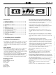
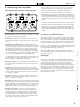
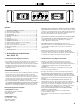
3.3 Rear Panel Sockets and Switches
1 Channel A output Speakon socket: Normal output is on pins 1+
hot, 1- cold. Channel B’s output is also wired to this socket to enable
a single NL4 to provide both channels and to facilitate easier wiring
in bridged mode. Channel B is wired pins 2+ hot, 2- cold. Similarly
channel C’s output Speakon socket carries Channel D’s output. Check
the table on the rear panel for details.
2 Link switch: Press this switch to link the input of the channel to its
immediate left. Multiple channels may be linked using these switches
so, for example, to link all outputs to input A, press all three switches
IN and use input A only. The front panel attenuators will still operate
independently when channels are linked.
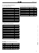
3 PRC switches: Each channel of the amplifier may be power limited
independently using these pairs of switches in three stages, offering 2,
4 and 6 dB of Power Reduction Control.
PRC
Power Reduction Control
S1 S2
0 dB
–2 dB
–4 dB
–6 dB
The settings for these switches are on the rear panel for quick reference.
4 Input XLR sockets: Connect signal inputs to these sockets, wired
pin2 hot, 3 cold, 1 ground. For sensitivity and impedance of these
inputs, please see the technical specifications.
5 Bridged (mono) switch (A&B): Press this switch to run this pair of
amplifier channels in bridged mode. To run C&D bridged, press the
switch on the far left of the panel, beside channel D’s input XLR.
6 Fan outlet: The variable speed fans suck air in through the front vents
and out through the back of the amplifier. Please see maintenance on
chapter 4.1 for recommendations on how to clean this and the front
foam sections.
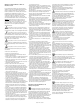
4. Looking After Your Amplifier
4.1 Maintenance
These maintenance instructions are for use by qualified personnel only.
Before any routine maintenance, please ensure that your amplifier is
disconnected from the mains supply! The filter behind the air intake
apertures on the front of your amplifier should be cleaned or replaced
periodically, e.g. 12-24 months. (Filters in amplifiers located in more
‚dirty‘ atmospheres may require more frequent maintenance). The filter
should be ‚dry‘ cleaned, using a vacuum cleaner preferably. Running
the unit without a filter is not recommended unless it is within a ‚clean
room‘. Replacement filter material is available. If the fan vents on the
rear of the amplifier develop a build-up of dust/debris on the finger
guards, they can be cleaned with a dry paintbrush and a vacuum
cleaner. The casework of the amplifier may be cleaned with a lightly
dampened cloth — do not use any solvents as they will damage the
paint finish and could remove printing. If you have any doubts about
carrying out maintenance, please refer to a service engineer or contact
your local dealer.
Leave enough space for proper ventilation!
PRC
Bridge
C&D
Bridge
A&B
Bridge
Mode
Link
C&D
S2S1
Serial No.
Input
Output Connections
Class 3 Wiring on Outputs
D C B A
D+ C+ B+ A+
D– C– B– A–
D+ B+
D–
1+
1–
2+
2–
B–
PRC
D
Output
PRC
S2S1
C
Link
B&C
PRC
S2S1
B
Link
A&B
PRC
S2S1
Power Reduction Control
1: Gnd
2: Sig+
3: Sig–
2
1
3
A
ABCD
S1 S2
0 dB
–2 dB
–4 dB
–6 dB
230 V~ 50/60 Hz
Current Consumption
15 A
CAUTION
RI SK O F E LE CTR IC
SH OC K. DO N OT OP EN.
CAUTION
Al l ve nts o n f ro nt an d re ar of u nit
mu st n ot be ob st ruc te d
Do n ot remo ve co ve rs
Th is u nit m ust b e e ar th ed
To red uc e t he risk o f fi re o r e le ct ric
sh oc k, do n ot ex pos e th is ap par at us
to r ai n o r moi st ure
To red uc e t he risk o f fi re r ep lac e th e
th e fu se wi th th e s am e typ e
No u se r s er vic ea ble p ar ts in sid e.
Re fe r ser vi cin g to qu al ifie d ser vi ce
pe rs on el
Mo un t in ra ck on ly.
1
2
3 4
5
6