
User guide


FIRNET Controller 1.1
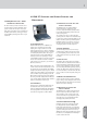
1 SPEAKER Key
• Selects a speaker-specifi c fi lter set from the FIR-
NET speaker series database
2 SCENE Key
• Loads scenes setups from the FIRNET database
and stores them to the database
3 LEVEL Key
• Adjusts input and output levels in the range of -60
dB to 12 dB
• Increment = 0.1 dB in the range of 12 dB to -12 dB
• Increment = 0.5 dB below -12 dB
4 DELAY/PHASE Key
• Adjusts delay time up to 500 ms for the FIRNET
controller’s inputs
• Adjusts delay time up to 25 ms for the FIRNET
controller’s outputs
• Inverts the phase position of the audio signal rout-
ed to the FIRNET controller’s inputs and outputs
5 ADMIN Key
• Locks keys to prevent unauthorized or unintentio-
nal handling
• Selects the audio signal input and associated
options
• Adjusts peak analog input and output levels to
match FIRNET to upstream or downstream audio
devices
• Edits the IP address, controller name, and display
contrast
• Serves to select the delay unit of measure
(ms, m, ft, samples) and enter the surrounding
temperature to calculate the speed of sound
6 AES IN LED Display
• Lights up blue when the FIRNET controller’s
digital AES/EBU IN signal input is selected
• Extinguished when the FIRNET’s analog signal
inputs are selected
7 EXT SYNC LED Display
• This LED lights up blue when an external AES/EBU
signal is enabled for the FIRNET’s synchronization
option and the device receives an incoming signal.
• Extinguished when the controller’s internal syn-
chronization is selected
8 INPUT LED Displays (10 LEDs, green/yellow/red)
• Green segment: Audio input level in the range of
-48 to -12 dB at full scale
• Yellow segment: Audio input level in the range of
-12 to 0 dB at full scale
• Red segment: Audio input level is overdriving the
AD converter
Note: An overdriven AD converter generates
distortion that the FIRNET’s limiter cannot sup-
press. If the red LED lights up, set the FIRNET’s
input gain to a higher value (see the section Setting
Peak AD Level in the Adjusting Parameters chapter)
or reduce the source audio device’s output level!
Be sure to heed the gain level recommendations for
connected amps, particularly when operating an
FP10000Q power amp.
9 LCD
• 2 x 24 characters
• Shows in normal operating mode the controller
name, the selected fi lter, and the existence of a
network link
• Shows options and editable parameters when you
access a menu
10 OUTPUT LED Displays
(10 LEDs, green/yellow/red)
• Green segment: Audio input level in the range of
-48 to -12 dB below the limiter value
• Yellow segment: Audio input level in the range of
-12 to 0 dB at below the limiter value
• Red segment: Limiter is attenuating the audio
input level. The given output is muted (LED lights
up continuously)
11 Back Key
• Returns to the next higher menu level
• Exits edit windows without assigning adjusted
values
• Adopts unconfi rmed parameter changes with Enter
12 Navigation Keys
• Navigates to the next or previous menu option
• Selects and changes parameters in the edit
windows
• Top key: Arrow up while scrolling in the menus
• Bottom key: Arrow down while scrolling in the
menus
• Right key to adjust parameter values (higher
numerical values)
• Left key to adjust parameter values (lower
numerical values)
• Enter key to confi rm the adjusted value
13 Reset Button
The FIRNET controller reboots after 10 seconds,
and then loads the most recent settings. Unsaved
settings are not retained.
14 Soft Reset and Hard Reset key combinations
The FIRNET offers two more reset functions:
Soft Reset: (Admin+Back+Enter for 3 seconds)
Loading the default preset Null
Functions:
• No speaker/ no fi lter selected
• No signal routed to the exits
• All FIR initial coeffi cients set to 0
• No fi lters set; fi lter must be reloaded!
• X-Over set to bypass
• Input/ output gain set to 0
• Delay parameter set to 0
• IIR EQs all input gains set to 0,
• IIR EQs output set to bypass (LIPAN Off) and gain to 0
• All limiters set to + 10dB threshold
• Admin parameters remain unchanged
• Outputs 1-4 muted
Hard Reset: Factory default
(Speaker+Admin+Back for 3 seconds)
Functions:
• Filter banks deleted
• Admin: Keylock deactivated
• Input assign A/B
• Analog input source
• Sample rate 96 kHz
• Dig Clk Sync: internal
• Delay unit: ms
• Temperature: 20°C
• Display contrast: 15
• Device name 0
• Max input: + 18 dBu
• Max. output + 6 dBu (setting for VX 2400)
• IP not reset
5 Front - Control Readouts and Displays: