
Installation Instructions

currentlighting.com
© 2022 HLI Solutions, Inc. All rights reserved. Information and specifications subject to change
without notice. All values are design or typical values when measured under laboratory conditions.
Page 2 of 4
Rev 08/01/22
NXSMP2-HMO_LMO_install_sheet_R01
93147265 Rev. A
DESCRIPTION
NXSMP2 Series Digital Smart Sensors are a combination PIR Occupancy Sensor and Closed Loop Daylight sensor specifically
designed for installation within a lighting fixture and ceiling mount applications. When used with corresponding NXFM2 Series
Fixture Module, the NXSMP2 Series Sensors can be programmed to provide Automatic On/Off control based on occupancy and/
or Automatic Light Level Control based on the amount of ambient daylight. The NXSMP2 Series sensors also include a wireless
2.4GHz radio and Integral Bluetooth® for wireless networking and ladder-less programming from a mobile device. The NXSMP2
Series Digital Sensors can be configured via the NX Lighting Controls mobile application and can be utilized in either stand alone
or networked applications with other NX Room Control or NX Network devices.
NXSMP2HMO/LMO INSTALLATION
NXSMP2-HMO/LMO is Rated for Indoor and Outdoor Use
The NXSMP2-HMO/LMO is designed to be mounted on flat surface either for in-fixture or ceiling mount applications.
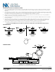
INSTALLATION FOR CEILING MOUNT DEPLOYMENT
1. Choose a mounting location on ceiling with a flat surface where the sensor face and sensor lens will be oriented in the downward
position as close to level as possible. NOTE: The sensor should be clear from obstructions to ensure proper detection.
2. Once a position is selected a 1-2/5” to 1-1/2” round opening in the ceiling or junction box needs to made in order for the sensor to
slide into position. After the sensor is in position use the provided locking ring and gasket to secure the sensor in place. NOTE: Do
not over tighten the locking ring and gasket. This can cause damage to the sensor gasket.
3. After the sensor is mounted locate the miniature 4-pin SmartPORT positioned on the back of the sensor. Using a NXCBL-P plug
the miniature 4-pin SmartPORT connector into the back of the sensor.
4. Once the cable has been connected to the sensor using the opposite end of the NXCBL-P utilize the RJ45 port and CAT5e cable
to connect the sensor to a NX Room Controller on the FX SmartPORT. NOTE: If using multiple NXSMP2 sensors in a daisy chain
configuration Qty:(2) NXCBL-P must be used to provide in and out connection.
5. Once all connections are made take one of the provided MAC Address labels and affix it to the reflected ceiling plan, layouts,
drawings or project documentation identifying its location. This will be used by the Field Engineer to program and calibrate the
sensor during system startup.
FOR SENSOR PROGRAMMING SEE QUICK STARTUP GUIDE FOR DISCOVERING AND CONFIGURING NXSMP SERIES SENSORS.
SPECIFICATIONS
CONSTRUCTION
• Housing: ABS (UL-945VA) Flame
Class Rating, UV Inhibitors
• Color: White, Gray, Black
• 3.2oz (90.7g)
• Overall Dimensions: 1.87” (47.50mm)
H x 3.48” (88.39mm) W
• Mounting Barrel: 1.31” (33.27mm) H x
1.18” (29.97mm) W
• Complies for use in a plenum area
• IP65 Rated for Indoor and Outdoor use
MOUNTING
• Mounts directly in 1.2” diameter
aperture, secured by supplied nut on
threaded housing
• Recommended (HMO) Max Outdoor
Mounting Height: 40 ft. (12.19m)
• Recommended (HMO) Max Outdoor
Mounting Height: 45 ft. (13.72m)
• Recommended (LMO) Max Mounting
Height: 16 ft. (4.27m)
• Recommended (LMO) Minimum
Mounting Height: 8 ft. (2.43m)
ELECTRICAL
Input:
• Input Voltage: 12-24VDC supplied by
NXFM2 (NX Fixture Module)
• Power Consumption: 30mA
• Wiring: Uses NXV
STANDBY POWER (W):
• 120VAC: 0.1W
• 277VAC: 0.1W
• 347VAC: 0.1W
OPERATING ENVIRONMENT
• Rated for Indoor and Outdoor Use
• Operating temperature: -40°F to
185°F (-40°C to 85°C)
• Relative humidity (non-condensing)
0% to 95%
WIRELESS
• 2.4GHz: IEEE 802.15.1 based
• Bluetooth® Version V5.2
SENSORS
• Detection Technology: Passive
Infrared Sensor
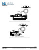
SENSORS (Continued)
• 1:1.4 Coverage Pattern (HMO) (mounting
height: coverage radius)
• 1:3 Coverage Pattern (LMO) (mounting
height: coverage radius)
• (HMO) Max Outdoor Mounting Height 40ft
• (HMO) Max Indoor Mounting Height 45ft
• (LMO) Max Mounting Height 16ft
• LED Indicator (Red) indicates
occupancy detection
PROGRAMMING INTERFACE
• NX Lighting Controls Mobile App
• NX Area Controller (NXAC) for
Network Applications
CERTIFICATIONS
• cULus Listed
• Complies with FCC Part 15.247
• FCC ID: YH9NXSMP2
• IC: 9044A-NXSMP2
WARRANTY
• 5-year limited warranty
• See HCS Standard Warranty for
additional information