
Installation Instructions

currentlighting.com
© 2022 HLI Solutions, Inc. All rights reserved. Information and specifications subject to change
without notice. All values are design or typical values when measured under laboratory conditions.
Page 3 of 4
Rev 08/01/22
NXSMP2-HMO_LMO_install_sheet_R01
93147265 Rev. A
INSTALLATION FOR INFIXTURE DEPLOYMENT
6. Choose a mounting location on the housing or lens with a flat surface where the sensor face and sensor lens will be oriented
in the downward position as close to level as possible. NOTE: The sensor should be clear from obstructions to ensure proper
detection.
7. Once a position is selected a 1-2/5” to 1-1/2” round opening in the housing or lens needs to made in order for the sensor to slide
into position. After the sensor is in position use the provided locking ring and gasket to secure the sensor in place. NOTE: Do not
over tighten the locking ring and gasket. This can cause damage to either the fixture or gasket.
8. After the sensor is mounted locate the miniature 4-pin SmartPORT positioned on the back of the sensor. Using a NXCBL-I or
NXCBL-O insert the connector into the back of the sensor.
9. Once the cable has been connected to the sensor connect the opposite end of the NXCBL to additional NX Devices mounted
inside the luminaire.
10. Once all connections are made take one of the provided MAC Address labels and affix it to the outside of the luminaire in a
visible location. This will be used by the Field Engineer to program and calibrate the sensor during system startup. NOTE:
Provide the additional labels in packaging for use in field on layouts, drawings or similar project documentation.
11. After install is complete perform end of line testing as provided by HCS for verification of performance.
FOR SENSOR PROGRAMMING SEE QUICK STARTUP GUIDE FOR DISCOVERING AND CONFIGURING NXSMP SERIES SENSORS.
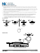
MOUNTING DETAIL
HOLE DETAIL
Ø 1.44”
NXSMP2-HMO/LMO
(Prole View)
NXSMP2-HMO/LMO
(Prole View)
NXSMP2-HMO/LMO
(Prole View)
NXSMP2-HMO/LMP
(Prole View)
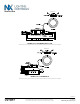
WIRING DIAGRAM
NXSMP2 Sensor with NXFM2-1R2D-I-UNV
NXSMP2 Sensor
NXSMP2 Sensor
Pink (-)
NXFM2-1R2D-I-UNV
Pink wire replace previous gray wire. Unit with a gray instead of pink wire should be wired as the pink wire shown in the diagram.