
User's Manual


Figures and Diagrams
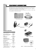
Figure 1. Wireless IQ standard equipment ............................................................................................................... 1
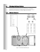
Figure 2. Base station with front door open.............................................................................................................. 2
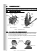
Figure 3. Communicator controls ............................................................................................................................. 4
Figure 4. Correct wearing of the headset .................................................................................................................. 4
Figure 5. Registration buttons and indicators ........................................................................................................... 6
Figure 6. Belt-pac battery-release latch .................................................................................................................... 7
Figure 7. Headset battery-release latch ..................................................................................................................... 7
Figure 8. Batteries in charger ................................................................................................................................... 8
Figure 9. Battery charger AC adapter connection .................................................................................................... 9
Figure 10. 230VAC adapter wiring for battery charger .......................................................................................... 10
Figure 11. Typical drive-thru store layout ............................................................................................................... 13
Figure 12. Typical tandem and dual drive-thru layouts ............................................................................................ 14
Figure 13. Open base station showing four screw holes ........................................................................................... 15
Figure 14. Remote antenna mounting on wall bracket ............................................................................................ 16
Figure 15. Microphone ............................................................................................................................................ 18
Figure 16. Microphone unit and foam inserts shown in typical speaker post installation ....................................... 18
Figure 17. Open the low-profile speaker ................................................................................................................. 19
Figure 18. Mark speaker post or menu board through wire hole in rear panel of SP2500LP
speaker assembly ................................................................................................................................... 19
Figure 19. Screw the self-tapping screws through holes in rear panel of SP2500LP speaker box .......................... 19
Figure 20. SP2500LP cable connections .................................................................................................................. 19
Figure 21. Installing the SP2000A .......................................................................................................................... 20
Figure 22. SP2000A cable connection ..................................................................................................................... 20
Figure 23. External message repeater connections .................................................................................................. 22
Figure 24. Typical tandem drive-thru layout ........................................................................................................... 29
Figure 25. S2 switch on Switcher Board .................................................................................................................. 31
Figure 26. Base Station internal controls and indicators ......................................................................................... 35
Figure 27. Base station jumper settings ................................................................................................................... 36
Figure 28. Base station DIP switch functions .......................................................................................................... 37
Figure 29. Typical Wireless IQ Base Station block diagram .................................................................................... 39
Wiring Diagrams ....................................................................................................................................... 43
Figure 30. Full-Duplex Wireless IQ with VDB but no Switcher Board ..................................................................... 44
Figure 31. Full-Duplex Wireless IQ with VDB, Switcher Board, DM1 or DM3 Microphone and IC300 ................. 45
Figure 32. Full-Duplex Wireless IQ with VDB, Switcher Board and DM1 or DM3 Microphone ............................. 46
Figure 33. Half-Duplex Wireless IQ with VDB but no Switcher Board .................................................................... 47
Figure 34. Half-Duplex Wireless IQ with VDB and Switcher Board ........................................................................ 48
Figure 35. Dual-Lane Wireless IQ Primary to Secondary Base Station Connections ................................................ 49
Figure 36. Tandem Wireless IQ Primary to Secondary Base Station Connections ................................................... 50
© 2015 HM Electronics, Inc.
The HME logo and product names are registered trademarks of HM Electronics, Inc. All rights reserved.
Illustrations in this publication are approximate representations of
the actual equipment, and may not be exactly as the equipment appears.
HM Electronics, Inc. is not responsible for equipment malfunctions due to erroneous translation of
its installation and/or operating publications from their original English versions.