
User Manual


7
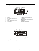
BASE STATION SETUP
Connect equipment and make adjustments described below to the rear panel of the base station where indicated
on this illustration.
1. RECEIVE Antenna Connector — Connect the receiver antenna to this BNC connector. The color band
(if present) around the antenna should match the color dot (if present) near the connector on the base.
2. USB Interface Connector — To interface the PRO850 with a PC using a computer interconnect cable
with a USB 1.1 compliant type-B connector, connect the cable from this connector to the PC.
3. RS-232 Interface Connector — To interface the PRO850 with a PC using a computer interconnect cable
with a 9-pin RS-232 serial interface connector, connect the cable from this connector to the PC.
4. Multiple Base Station Interface Connector — Use this RS-422 serial interface to connect master and
slave base stations together.
In the 2-Wire ISO+ mode, the headset connector on
the front panel of the base station is disabled from
normal headset functions and becomes available for
connection to devices other than a headset.
In the 2-Wire mode;
• If you have an RTS system, only one 2-wire cable
is needed for connecting bases. The switch on the
back panel of the base station must be set for RTS
TW. One cable carries both CH1 and CH2.
• If you have a ClearCom system, two cables are
needed for connecting base stations. The switch on
the back panel of the base station must be set for
CLEAR-COM.
In all multibase configurations, connect the Aux Out
from Slave 1 to the Aux In of the Master Base Station
and connect the Aux Out from Slave 2 (if present) to
the Aux In of Slave 1.
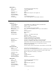
SECTION 2. EQUIPMENT SETUP
1 2 3 4 5 6 7 8 9 10 11 12 13 14 15 16 17 18 19