
User Manual


2
1 2 3 4 5 6 7 8 9 10 11 12 13 14 15
EQUIPMENT FEATURES
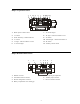
Base Station Front Panel Features
1. POWER switch
2. BELTPAC CONFIGuration connector
(RJ10 telephone handset cable connector)
3. WIRED STATUS lights
CH1 = Channel 1 intercom status
CH2 = Channel 2 intercom status
AUX = ISO+ mode
4. RECEIVER QUICK MENU buttons
5. RECEIVER STATUS lights
6. Arrow buttons (move curser around on menu)
7. ENTER button (selects function or setting)
8. CANCEL button (backs out of menus or
cancels operation)
9. Display screen
10. Multi-function knob (headset volume control;
adjustment for specific menu selections)
11. Local headset function lights
12. Local headset function select switch
13. Local headset TALK indicator light
14. Local headset TALK switch
15. Local headset connector
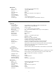
Base Station Rear Panel Features
1. Receiver antenna connector
2. USB type-B computer connector
3. 9-pin RS-232 computer connector
4. RS-422 interface
(for connecting two or more bases together)
5. Channel 1 null adjustment
6. Channel 1 2-wire intercom interface connector
7. ClearCom RTS select button
8. Channel 2 2-wire intercom interface connector
9. Channel 2 null adjustment
10. Channel 1 RJ45 4-wire intercom interface
connector
11. Channel 2 RJ45 4-wire intercom interface
connector
12. Auxiliary input connector
(accepts XLR plug or standard phone plug)
13. Auxiliary output connector
14. Paging output connector
15. 12-14VDC power jack
16. Page relay connector
17. Alert relay connector
18. Transmitter antenna connector
19. Grounding screw
1 2 3 4 5 6 7 8 9 10 11 12 13 14 15 16 17 18 19