MDL Series Programmable DC Electronic Load Models: MDL001, MDL002, MDL200, MDL252, MDL305, MDL400, MDL505, MDL600 USER MANUAL Documentation Provided By HMC Electronics 33 Springdale Ave. Canton, MA 02021 http://www.hmcelectronics.
Safety Summary The following general safety precautions must be observed during all phases of operation of this instrument. Failure to comply with these precautions or with specific warnings elsewhere in this manual violates safety standards of design, manufacture, and intended use of the instrument. We assume no liability for the Customer’s failure to comply with these requirements. ENVIRONMENTAL CONDITIONS This instrument is intended for indoor use, pollution degree 2 environments.
DO NOT SERVICE OR ADJUST ALONE Do not try to do some internal service or adjustment unless another person capable of rendering first aid resuscitation is present. Safety Symbols Direct current Alternating current Both direct and alternating current Protective earth (ground) terminal Attention (refer to accompanying documents) WARNING The WARNING sign denotes a hazard. It calls attention to a procedure, practice, or the like, which, if not correctly performed or adhered to, could result in personal injury.
Compliance Statements Disposal of Old Electrical & Electronic Equipment (Applicable in the European Union and other European countries with separate collection systems) This product is subject to Directive 2002/96/EC of the European Parliament and the Council of the European Union on waste electrical and electronic equipment (WEEE), and in jurisdictions adopting that Directive, is marked as being put on the market after August 13, 2005, and should not be disposed of as unsorted municipal waste.
Table of Contents Safety Summary ........................................................................................2 Compliance Statements.............................................................................4 Product Overview .....................................................................................8 Description .................................................................................................................................. 8 Features ..............................
External ON/OFF Control Connection ......................................................................................... 35 Mainframe Extension Connections ............................................................................................. 35 PC Control Connection ............................................................................................................... 36 Operation ...............................................................................................
Setting Up Von Function ......................................................................................................... 61 Save and Recall Operation ......................................................................................................... 62 Module Controlling Link............................................................................................................. 63 Voltage Failure Indication .................................................................................
Product Overview This section describes the main features and menus of the MDL Series DC Electronic Load. The MDL Series is comprised of two parts, mainframes and modules. The mainframes mentioned are the MDL001 mainframe and the MDL002 mainframe extension. Modules in this series include the MDL200, MDL252, MDL305, MDL400, MDL505, and MDL600. Unless otherwise noted, this document will refer to all of these instruments as “electronic load”.
Features CC/CV/CR/CW/CZ operating modes Removable modules for easy system flexibility Bright VFD display for both mainframe and modules Power range up to 2400 W (4800 W with mainframe extension) Supports up to 16 channels with mainframe extension Operate identical modules in parallel mode for high current applications Synchronous load on/off function 16-bit voltage and current metering providing high resolution of 0.1 mV and 0.
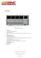
Front Panel Figure 1 - MDL Series Front Panel 1) VFD DISPLAY Displays electronic load information. 2) MODULE PANEL KEYS Controls module functions. Refer to Module section for more details on the use of these keys. 3) ADJUSTMENT KNOB Used to change parameters. 4) MAINFRAME FUNCTION KEYS Controls each channel’s operating status. Refer to Mainframe section for more details on the use of these keys. 5) MAINFRAME NUMERIC ENTRY AND SHIFT KEYS Refer to Mainframe section for more details on the use of these keys.
Rear Panel Figure 2 - MDL Series Rear Panel 1) GPIB interface 2) Input terminal of module 3) Remote measurement and external input control terminal 4) Current monitoring output 5) Digital I/O and VF output terminal 6) Extended module interface 7) AC Power input socket 8) USB interface 9) Line voltage selection switch (110V/220V) 10) Trigger I/O and load on/off terminals 11) LAN interface 12) RS-232 interface 13) Not used – for factory use only 11 Documentation Provided By HMC Electronics 33 Springdale A
Protection Functions The electronic load has the following protection functions: Overvoltage protection (OVP), overcurrent protection (OCP), overpower protection (OPP), overtemperature protection (OTP), and local and remote reverse voltage protection (LRV/RRV). The mainframe will act appropriately once any of the above protections are active. You can press any button on the front panel to restore the protection function.
Panel Operations 1. Power on the electronic load. 2. 3. 4. 5. 6. 7. VFD Display Self-test Sync On Set Von Meter Protect Press Shift + ⑧ to enter Configuration menu. List Ext. Ctrl Set About Exit Max Power Set Alimit State Alimit Point Alimit Delay Press key to select and press Enter to go into protection Plimit Point menu. Plimit Delay OnTimer State OnTimer Set Exit Press key to select and press Enter. Select On and press Enter to confirm.
Overpower Protection (OPP) The electronic load includes both hardware and software OPP features. Hardware OPP – In the event that the electronic load’s input power exceeds the set power protection limit, the hardware OPP will limit the power. Once the hardware OPP is triggered, the status register’s OP bit will be set. When the hardware OPP is removed, the status register’s OP bit will be reset. Hardware overpower protection will not turn the electronic load’s input off.
Operations to Clear the OPP State Check whether the input power is within the rated power range or the programmed protection ranges. If it is outside the range, disconnect the device under test. Then press any key on the front panel or remotely send command PROTection:CLEar. The OPP displayed on the front panel will turn off and the electronic load exits OPP protection state.
Menu List The following menus can be viewed on the VFD display. Use keys to scroll through the menu list and press Enter key to enter the selected menu function. Use keys to scroll through the VFD screen and press Enter key to enter its submenu. Press Esc to go back to the previous menu selection. Pressing number keys can directly select a channel. Setup Menu Press Setup key to enter the setup menu.
System Menu Press Shift + ⑦ key to enter the System menu. MENU INITIALIZE INITIALIZE DEFAULT SET Resume all configuration to default settings POWER ON SET BUZZER SET LOAD ON KNOB TRIGGER SOUR.
RS232 SET PARITY SET HANDSHAKE SET GPIB ADDRESS ETHERNET SET EXPAND MODULE LANGUAGE SET ABOUT Set up the communication parity NONE (DEFAULT) ODD EVEN Select the handshake protocol NONE (DEFAULT) CTS/RTS XON/XOFF GPIB address setting GPIB ADDRESS SET Set up communication address Ethernet settings GATEWAY SET Gateway setting IP SET IP setting MASK SET Mask setting PORT SET Port setting EXIT Module expansion ON Enable the function OFF (DEFAULT) Disable the function Communication protocol SCPI (DEFAULT)
Configuration Menu Press Shift + ⑧ key to enter the channel Configuration menu.
EDIT LIST EXT.
Installation Inspection This instrument was carefully inspected before shipment. Upon receipt, inspect the instrument for damage that might have occurred during transit. If any sign of damage is found, please notify your B&K Precision distributor. The following standard and optional accessories are provided with each mainframe or module.
Installing Modules CAUTION : Static electricity may damage load modules. Please install modules according to standard electrostatic prevention. Avoid touching joints and circuit boards. One can install any combination of modules up to 2400 W total in the MDL001 mainframe in any order. This also applies to the MDL002 mainframe extension, allowing a maximum of 4800 W total when connecting the MDL001 and MDL002 together.
Figure 3b - Module Installation 4. Insert and slide the selected modules into the slot. Figure 3c - Module Installation 5. Insert and tighten module screws on rear panel. 23 Documentation Provided By HMC Electronics 33 Springdale Ave. Canton, MA 02021 http://www.hmcelectronics.
Figure 3d - Module Installation 6. Install more modules in other slots following the same process (steps 2 through 5). 7. Reconnect the power cord. Channel Number The channel number for all modules is determined by the location of the modules in relation to the mainframe and ordered from right to left. With the MDL001 mainframe, the total number of channels is 8. Channels 1 and 2 are next to the mainframe front panel, while channels 7 and 8 are located on the left side.
The following figures show examples of how channels are assigned when single-channel and dualchannel modules are installed. Figure 5 - Channel Number Order When Installing Four Single-Channel Modules Figure 6 – Channel Number Order When Installing Two Single-Channel Modules and Two Dual-Channel Modules Note : Mainframe extension module channels are numbered 11-18. Location The operating temperature of the MDL Series DC Electronic Load is 0 to 40 ℃.
cabinet, please avoid installing the load near the fan, since it may limit air circulation of the load. If you are installing equipment on top of your electronic load in the cabinet, use a filler panel above the unit to ensure adequate air circulation. The MDL Series can be placed in a standard 19-inch rackmount shelf. Rack mount kit IT-E153A is available for use with mainframe (MDL001) and mainframe extension (MDL002). When mounted, there is no need to remove the bottom studs.
Figure 8 - Module Outline Diagram Note : Dimensions are in millimeters (mm). Input Voltage Selection The electronic load can work under 110/220V±10% AC input, identified by an input line voltage switch on the rear (refer to Figure 9). If the indicated line voltage does not match your region, please use the switch in the back of the unit to choose your input line voltage, install appropriate fuse (refer to Table 1 - Fuse Table below), and then insert power cord.
Figure 9 – Input Voltage Selection Turn-On Checkout When you turn on the electronic load, the front-panel display will light up briefly while the electronic load performs its power-on self-test. The following table shows the procedure of the self-test. Mainframe VFD Display Description BOIS Ver 1.20 VFD displays software version SYSTEM SELF TEST System self-check CH1/2/3/4/5/6/7/8 SCAN… □7□5□3□1 e.g.:CH01 CV OFF Vdc=0.0000V Adc=0.0000A Wdc= 0.
If the Electronic Load Does Not Turn On Use the following troubleshooting steps to help solve problems you might encounter when turning on the instrument: 1) Verify that there is AC power to the electronic load. First, verify that the power cord is firmly plugged into the power receptacle on the rear panel of the electronic load. You should also make sure the power source you plugged the electronic load into is energized. Then check to see that the electronic load is turned on.
Load Connection WARNING : To satisfy safety requirements, load wires between the electronic load and the device under test (DUT) should have a current rating high enough not to overheat while carrying the short-circuit output current. Never make connections between the electronic load and a DUT while the electronic load inputs are turned ON and/or the DUT has live power at its output.
There are two positive terminals and two negative terminals on the rear panel of every module. Single terminal connection is adequate when the input current is less than 30 A. WARNING : Each terminal can carry up to 30 A current. Double-terminal connection is needed when the input current is more than 30 A. Refer to Figure 11 - Connection of Load and Device Under Test (DUT) for double-terminal connection.
There are two input connectors. One is the electronic load’s input measurement terminal and the other is the Vsense measurement terminal. When Vsense is connected to device to be measured, the electronic load will switch to Vsense mode automatically. There is no need to change a setting in the menu and the front panel of the module will show “sense”. CAUTION : The electric potential on the positive terminal of Vsense connector must be higher than the negative terminal.
Mainframe 8-pin Control Connector The mainframe’s 8-pin control terminal on the rear panel is shown below. This is used for external trigger and ON/OFF control connections.
External Trigger Connections There are five kinds of trigger modes: 1) Front panel TRIG trigger mode 2) Rear panel trigger mode 3) BUS trigger mode 4) Timer trigger mode 5) Hold trigger mode Setting these modes is done through the System menu (Shift + ⑦) under . Press Enter to confirm setting and Esc to exit menu. Trigger Modes 1) To use front panel trigger mode, first set the trigger source as MANUAL. Press Trig to start panel trigger mode.
External ON/OFF Control Connection ON/OFF IN (pin 3 of rear 8-pin Control Connector) is used to toggle the multi-channel electronic load inputs ON or OFF. When ON/OFF IN pin receives a TTL level pulse (>10us), the ON/OFF state of the load will toggle. SYNC ON SET function can be set to ON for multiple channels to toggle more than one channel at a time. ON/OFF OUT (pin 4 of rear 8-pin Control Connector) indicates ON/OFF state of the multi-channel electronic load.
PC Control Connection The MDL Series DC Electronic Load can achieve remote control via USB, RS-232, LAN, or GPIB interface, but only one interface can be used at a time. Choose the interface via the System menu (Shift + ⑦). Connect communication cable before powering on. Do not hot plug, as it may damage the communication interface of the electronic load. The following procedure shows how to connect the RS-232 cable between the electronic load and PC. Procedure: 1. Connect RS-232 cable. 2.
Operation Operating Modes The electronic load can work in the following modes: 1) Constant current (CC) operation mode 2) Constant voltage (CV) operation mode 3) Constant resistance (CR) operation mode 4) Constant power (CW) operation mode 5) Constant impedance (CZ) operation mode Constant Current (CC) mode In this mode, the electronic load will sink a current in accordance with the programmed value regardless of the input voltage.
Immediate Current Value Set the current level via front panel or by sending SCPI command CURR . If the load is in CC mode, the new current level setting immediately changes the input at a rate determined by the slew rate. If the load is not in CC mode, the current level setting will be saved for use until mode is switched to CC mode. Transient Current Level A/B transient current level can be set on the front panel or by remote operation.
Between the 10% and 90% region, the slew rate can be measured by observing the steepest slope portion. In case of very large load changes, e.g. from no load to full load, the actual transition time will be larger than the expected (measured) time. For this reason, the firmware allows the user to program slew rate values outside of the specified slew rate ranges.
Transient Voltage Level A/B transient voltage level can be set on front panel or by remote operation. The electronic load can continuously toggle between the two levels when transient operation is turned on. Constant Resistance (CR) Mode In this mode, the electronic load is equivalent to a constant resistance, as shown below. The electronic load will linearly change the current, according to the input voltage.
Constant Power (CW) Mode In this mode, the electronic load will consume a constant power. When input voltage increases, the input current will decrease, while power (P = V*I) will remain the same. Figure 20 - Constant Power Mode Ranges When working in CW mode, you can press the Setup key to enter the RANGE menu. Two overlapping ranges can be selected: LOW RANGE or HIGH RANGE. Power can be edited in either of the two ranges.
Ls + VS Rs Is - CL RL Figure 21 - Constant Impedance Mode Ranges When working in CZ mode, you can press the Setup key to enter the RANGE menu. Two overlapping ranges can be selected: LOW RANGE or HIGH RANGE. Impedance can be edited in either of the two ranges. Low range will supply higher accuracy and better resolution when you set lower impedance. If any value you set is outside the maximum value of the LOW RANGE, you should select HIGH RANGE.
Setting CV, CC, CR, CW, CZ Mode The following procedure will show you a basic example of how to set up your operation mode from the front panel. Panel Operations 1. Power on the electronic load. 2. Press keys to select the channel to be edited, such as channel 1. VFD Display Self-test CH01 CC OFF Vdc=0.0000V Adc=0.0000A Wdc=0.00W 3.
Local Operation Mainframe Panel The front panel keys are effective only in the local mode. When the load is powered on, it works in local mode automatically (unless any of the remote interfaces are connected to a device controlling it) and then you can select channel number and set parameters such as voltage or current via the front panel keys. When the load is repowered on, the mainframe will scan all the installed modules once again, and can recall the parameters from the last time it was powered off.
2. FUNCTION KEYS Key Description Chan This key is used to switch channels. Every module has its own channel number and can be selected from the mainframe panel. Save This key is used to save parameters. After selecting a channel and editing its parameters, press the Save key to save your settings into non-volatile memory. Up to 101 groups of parameters can be saved. Recall This key can be used to quickly recall a saved group of parameters from memory.
3. ENTRY/SHIFT KEYS Key ⓪ ① ② ③ ④ ⑤ ⑥ ⑦ ⑧ ⑨ Description These are number input keys. Esc This key can be used to exit any working state. This key is used for decimal. These keys are used to move up and down the menu selection. Enter This key is used to confirm selection. Shift This key is used to enter other menus and functions. Shift + ⑦ (System) Shift + ⑧ (Config) Shift + ⑨ (Program) Shift + ⓪ (Local) Shift + (Lock) Press this key combination to enter the System menu.
Module Panel Figure 23 - Module Front Panel 1. VFD DISPLAY Bright VFD display shows module‘s operating mode. 2. ROTARY KNOB Used to change parameter values. 3. PANEL KEYS Key Description A/B Switch A/B transient preset value. (single channel modules) L/R Switch the left/right channels. Press this key + rotary knob to control (dual-channel modules) the two channels. Short Used for short testing. This allows the load to simulate a short circuit at the input.
Tran On/Off Selects the transient mode. Press this key first to enable transient mode before running A/B transient operation and then send the triggering signal to run a program. Control module’s input on/off state 4. AIR INLET Module’s air inlet for cooling purposes. WARNING : Do not place any objects that may block or cover air inlet. Module Panel Lock Press Shift + key to lock current channel’s keys and knob operation. To unlock, press Shift + key again.
VFD Indicator Function Description The detailed illustration of the VFD and all indicator functions are as follows: Figure 24 - Load Module VFD Panel L/R is the indicator of the dual-channel module’s left/right channel. If you want to edit left/right channel parameters, first select the channel using the L/R key. Single-channel module will always display R. OFF indicates that the module input is off. When module input is enabled, OFF indicator will turn off.
Transient Operation Transient operation enables the module to periodically switch between two load levels, as might be required for testing power supplies. Transient operation can be turned on and off from the front panel (Tran and Trig keys). Before you turn on the operation, you should set the parameters associated with the transient operation. The parameters include: A level, A width, B level, B width, and transient testing modes.
Figure 25 - Continuous Transient Operation Current Waveform Pulse In this mode, the electronic load generates a transient pulse of programmable width when pulse transient operation is in effect. In pulse mode, you can set A/B level, A/B width, and A/B slew rate via the mainframe keypad. The electronic load will automatically switch to A level after maintaining A width time. Then it will switch to B level. The electronic load will not switch to A level again until the instrument receives the pulse signal.
Toggle In toggle mode, the electronic load will switch between A level and B level when receiving a trigger signal after the transient operation is enabled. The following picture shows the current waveform in toggle transient operation. Figure 27 - Toggle Transient Operation Setting Up A/B Transient Operation The following is a short tutorial of how to set up A/B transient operation for your electronic load. In this example, we will set up rise speed at 1 A/us and fall speed at 2 A/us.
A/B Transient Operation Tutorial Panel Operations VFD Display 1. Power on the electronic load. Self-test 2. Press keys to select the channel to be edited. In this example, we select channel 1. CH01 CC OFF Vdc = 0.0000V Adc = 0.0000A Wdc = 0.00W 3. Press Setup to enter the channel setup menu. Select and press Enter to change the operating mode to CC mode. Press Enter to confirm. CH01 Mode=CC RANGE=HIGH Iset=9.000A 4. Press key to select setting and press Enter.
12. Press Esc key to exit. 13. Press Shift + ⑦ to enter System menu. Press key to select and press Enter. Select and press Enter to confirm. CH01 CC OFF Vdc = 0.0000V Adc = 0.0000A Wdc = 0.00W MANUAL EXTERNAL HOLD BUS TIMER 14. Press Esc key to exit. CH01 CC OFF Vdc = 0.0000V Adc = 0.0000A Wdc = 0.00W 15. Press On/Off key to turn on the electronic load’s input. CH01 CC ON Vdc = 0.0000V Adc = 0.0000A Wdc = 0.00W 16.
List Operation List mode lets you generate complex sequences of input changes on a single channel with rapid, precise timing, which may be synchronized with internal or external signals. This is useful when running test sequences with a minimum amount of overhead. The parameters of List operation include the name, number of steps (2-84), step width time (20us3600s), and every steps’ set value and slew rate. The list file can be saved in non-volatile memory where it can be quickly recalled.
2. Press keys to select the channel to be edited. CH01 CC ON Vdc=0.0000V Adc=0.0000A Wdc=0.00W 3. Press Shift + ⑦ to enter System menu. Press key to select and press Enter. Select and press Enter to confirm. MANUAL EXTERNAL HOLD BUS TIMER 4. If electronic load is on, press On/Off key to turn off the electronic load’s input. CH01 CC OFF Vdc=0.0000V Adc=0.0000A Wdc=0.00W 5. Press Shift + ⑧ to enter Configuration menu. Press key to select and press Enter.
13. Set second step’s width time. Input value and press Enter key to confirm. Step 002 width = 5S 14. Set parameters for steps 3 through 5 in the same manner described above. 15. Set number of run cycles. Input value and press Enter to confirm. Repeat Count = 1 16. Select memory position to save list file. Input value and press Enter to confirm. CH01 Save list file = 17. Press key to select and press Enter. Select and press Enter to confirm. Fixed List 18.
List Mode Programming Example If in remote control mode, you can refer to the following example to edit List operation (refer to MDL Series Programming Guide for more information).
Triggered Operation Trigger Function Trigger operation can be used in the following operations: transient pulse output, triggered output, and list output. The electronic load has five kinds of trigger modes to synchronously trigger the tested instrument. Before enabling the trigger function, users should first select trigger source. Trigger Source 1) Manual trigger: When manual trigger mode is active, pressing the Trig key on the front panel will enable a trigger operation.
Input On/Off Operation During front panel operation, press the On/Off key to switch the input on/off state. Input On/Off operation will not affect the present settings. The load/unload speed of On/Off operation is not dependent on the rise/fall slew rate. When in remote control mode, you can send SCPI command “INPut ON” to turn the input on (refer to MDL Series Programming Guide for more information on remote commands).
When Von LATCH is enabled, the electronic load will begin sinking current if input voltage exceeds Von voltage. When the input voltage drops below the Von voltage value, the electronic load will still continue to sink current and the input remains on. Figure 30 - Von LATCH Load's Working Range Setting Up Von Function The following is a quick tutorial of how to set up the Von function for your electronic load. In this example, we will set the Channel 1 Von point to 5 V and enable Von latch.
4. Select and press Enter. Von Point Von Latch Exit 5. Set the Von Point. Input 5 and press Enter to confirm. Von Point Set = 5V 6. Press to select and press Enter. Set on/off state. Select On and press Enter to confirm. On Off 7. Press Esc key twice to exit menus. 8. Press On/Off key to turn on the electronic load’s input. The electronic load will begin sinking current at 5V.
To Recall Panel Operations VFD Display 1. To recall saved data, press the Recall key. It will ask for the Recall Recall Group Group number. 0 2. Input the Group number (0-100) you previously saved your parameters to and press Enter key to recall. Recall Group 9 Module Controlling Link There is an 8-pin terminal and current monitoring connector on every module’s rear panel. Figure 31 - Terminals on Single-Channel Module Rear Panel 63 Documentation Provided By HMC Electronics 33 Springdale Ave.
Table 3 - Module Terminal Pinout Pin Signal Description 1 GND Ground 2 VF Voltage fault indication terminal 3 DI Digital input terminal 4 DO Digital output terminal ⃝ I OUT Current monitoring output 5 SENSE + Voltage remote measuring terminal (+) 6 SENSE - Voltage remote measuring terminal (-) 7 EXT_PRG+ External analog controlling terminal (+) 8 EXT_PRG- External analog controlling terminal (-) Voltage Failure Indication When the electronic load is under OVP or reverse protec
Remote Sense Function When working in CC, CV, and CR mode, if the electronic load consumes a very large current, it will cause a voltage drop in the leads between the connected device and terminals of the electronic load. In order to ensure testing accuracy, the electronic load provides a pair of remote sensing terminals in the rear panel where users can sense the output terminal voltage of the connected device. Users should set the electronic load in REMOTE SENSE mode before using this function.
3. Press Setup key to enter the channel setup menu, press Enter key to enter the selection menu and press key to select the operating mode. Every step’s mode can be edited. Press Enter key to confirm. MODE= RANGE= Iset= 4. Press key to select . Press Enter to enter the menu and set the working current. For example, to set 1A, press ① and then Enter to confirm. Const Current Set= 1.000A 5. Press key to move the cursor to Vmax=82.
13. The MDL Series with mainframe extension can support a maximum of 16 channels. 0 represents the MDL001 mainframe and 1 represents the MDL002 mainframe extension. □7□5□3□1 indicates channels 1, 3, 5, and 7 have been equipped with electronic load modules. Active Channel 0:□7□5□3□1 1 : □□□□□□□□ 14. Select the channels to be tested. For instance, if you want to select channels 3 and 5, press number keys 3 and 5. ‘Y’ denotes the channel is selected.
0 ≤ Tpf ≤ (Ton+ T off) Tpf is test delay time 21. Repeat steps 17 through 20 and set the rest of the steps’ load on/off time. 22. Set condition for when to stop testing. COMPLETE means to stop Stop Condition test when all steps are completed. FAILURE means to stop test Complete when testing fails. Press keys to select condition and press Failure Enter to confirm. 23. Program chain is used when you need to link to the next file to be tested. For example, if you need to link to group 2, press 2.
Table 4 - Save Table PROGRAM 1 Sequence 1 2 3 4 5 6 7 8 9 10 Save Group 1 2 3 4 5 6 7 8 9 10 1 2 3 4 5 6 7 8 9 10 11 12 13 14 15 16 17 18 19 20 PROGRAM 3 1 2 3 4 5 6 7 8 9 10 Save Group 21 22 23 24 25 26 27 28 29 30 PROGRAM 4 Sequence 1 2 3 4 5 6 7 8 9 10 Save Group 31 32 33 34 35 36 37 38 39 40 1 2 3 4 5 6 7 8 9 10 41 42 43 44 45 46 47 48 49 50 PROGRAM 6 Sequence 1 2 3 4 5 6 7 8 9 10 Save G
Recall Test Files The following is a procedure of how to recall edited test files from the EEPROM. Panel Operations VFD Display 1. Press Shift + ⑨ to enter the Program menu. Run Program Recall Prog Edit Program Exit 2. Press key to select and press Enter. Input the saved program number and press Enter to recall the saved testing file. Program Select NO: 1 3. To run the program, press key to select and press Enter. PROG.01 Result: Stop 4.
USB Interface Use Type A to Type B USB cables to connect the electronic load and the PC. All electronic load functions are programmable over the USB. Press Shift + ⑦ on the front panel to enter the System menu. Select and choose . The USB488 interface capabilities of the electronic load are described below: The interface is IEEE 488.2 standard USB488 interface. The interface accepts REN_CONTROL, GO_TO_LOCAL, and LOCAL_LOCKOUT requests.
RS-232 Interface Use a cable with two COM interfaces (DB9) to connect the electronic load and PC. It can be activated by selecting in of the System menu. NOTE: There are two COM interfaces on the rear panel of the MDL001 mainframe: the left 9-pin COM interface is the RS-232 communication interface and the right 9-pin COM serial port connection is not for use. All SCPI commands are available through RS-232 programming.
RS-232 Flow Control The RS-232 interface supports the following flow control options. For each case, the electronic load will send a maximum of five characters after hold-off is asserted by the controller. The electronic load is capable of receiving as many as fifteen additional characters after it asserts hold-off.
Pin Signal Description 1 NC No Connection 2 TXD Transmit Data 3 RXD Receive Data 4 NC No Connection 5 GND Ground 6 NC No Connection 7 CTS Clear to Send 8 RTS Ready to Send 9 NC No Connection RS-232 Troubleshooting If you are having trouble communicating over the RS-232 interface, check the following: The computer and the electronic load must be configured for the same baud rate, parity, number of data bits, and flow control options.
Specifications Model MDL200 MDL252 MDL305 MDL400 MDL505 MDL600 0-80 V 0-80 V 0-500 V 0-80 V 0-500 V 0-80 V Input Ratings Input Voltage Input Current Low 0-4 A 0-3 A 0-3 A 0-6 A 0-3 A 0-12 A High 0-40 A 0-20 A 0-20 A 0-60 A 0-30 A 0-120 A 300 W 400 W 500 W 600 W Input Power 200 W 250 W 1 Channels 1 2 1 1 1 1 Minimum Low Operating Voltage High CV Mode 0.10 V at 4 A 0.15 V at 3 A 0.7 V at 3 A 0.15 V at 6 A 0.54 V at 3 A 0.
Model MDL200 MDL252 MDL305 MDL400 MDL505 MDL600 Transient Mode (CC mode) T1&T2 20us-3600s/Res:5us-10ms Accuracy 5us+100ppm Slew Rate 2 Low 0.0001-0.25 A/us 0.0001-0.2 A/us 0.0001-0.1 A/us 0.0001-0.25 A/us 0.0001-0.1 A/us 0.0001-0.25 A/us High 0.001-2.5 A/us 0.001-2 A/us Accuracy 0.001-1 A/us 0.001-2.5 A/us 0.001-1 A/us 0.001-2.
Supplementary Characteristics Memory capacity 101 Groups Recommended calibration period Once per year AC power input (selectable by switch on the rear panel) Option 1: 220 V ±10%, 50/60 Hz Option 2: 110 V ±10%, 50/60 Hz Cooling method Fan cool Environmental conditions This instrument is intended for indoor use in a pollution degree 2 environment.
SERVICE INFORMATION Warranty Service: Please go to the support and service section on our website at www.bkprecision.com to obtain an RMA #. Return the product in the original packaging with proof of purchase to the address below. Clearly state on the RMA the performance problem and return any leads, probes, connectors and accessories that you are using with the device. Non-Warranty Service: Please go to the support and service section on our website at www.bkprecision.com to obtain an RMA #.
LIMITED THREE-YEAR WARRANTY B&K Precision Corp. warrants to the original purchaser that its products and the component parts thereof will be free from defects in workmanship and materials for a period of three years from date of purchase. B&K Precision Corp. will, without charge, repair or replace, at its option, defective product or component parts. Returned product must be accompanied by proof of the purchase date in the form of a sales receipt.
22820 Savi Ranch Parkway Yorba Linda, CA 92887 www.bkprecision.com © 2013 B&K Precision Corp. Printed in China v072413 Documentation Provided By HMC Electronics 33 Springdale Ave. Canton, MA 02021 http://www.hmcelectronics.