OM-926 211 123H 2006−01 Processes Air Plasma Cutting and Gouging Description Air Plasma Cutter AirForce 625 And ICE-40C Torch File: Plasma Cutters
From Hobart to You Thank you and congratulations on choosing Hobart. Now you can get the job done and get it done right. We know you don’t have time to do it any other way. This Owner’s Manual is designed to help you get the most out of your Hobart products. Please take time to read the Safety precautions. They will help you protect yourself against potential hazards on the worksite. We’ve made installation and operation quick and easy.
TABLE OF CONTENTS SECTION 1 − SAFETY PRECAUTIONS - READ BEFORE USING . . . . . . . . . . . . . . . . . . . . . . . . . . . . . . . . . . 1-1. Symbol Usage . . . . . . . . . . . . . . . . . . . . . . . . . . . . . . . . . . . . . . . . . . . . . . . . . . . . . . . . . . . . . . . . . . . . . . . . 1-2. Plasma Arc Cutting Hazards . . . . . . . . . . . . . . . . . . . . . . . . . . . . . . . . . . . . . . . . . . . . . . . . . . . . . . . . . . . . 1-3.
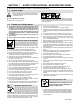
SECTION 1 − SAFETY PRECAUTIONS - READ BEFORE USING pom _4/05 Y Warning: Protect yourself and others from injury — read and follow these precautions. 1-1. Symbol Usage Means Warning! Watch Out! There are possible hazards with this procedure! The possible hazards are shown in the adjoining symbols. Y Marks a special safety message. . Means “Note”; not safety related. This group of symbols means Warning! Watch Out! possible ELECTRIC SHOCK, MOVING PARTS, and HOT PARTS hazards.
D D D EXPLODING PARTS can injure. D D D On inverter power sources, failed parts can explode or cause other parts to explode when power is applied. Always wear a face shield and long sleeves when servicing inverters. D FLYING SPARKS can cause injury. D Sparks and hot metal blow out from the cutting arc. Chipping and grinding cause flying metal. D Wear approved face shield or safety goggles with side shields. Wear proper body protection to protect skin.
1-3. Additional Symbols For Installation, Operation, And Maintenance HOT PARTS can cause severe burns. D Do not touch hot parts bare handed. D Allow cooling period before working on torch. D To handle hot parts, use proper tools and/or wear heavy, insulated welding gloves and clothing to prevent burns. MOVING PARTS can cause injury. D Keep away from moving parts such as fans. D Keep all doors, panels, covers, and guards closed and securely in place.
1-5. Principal Safety Standards Safety in Welding, Cutting, and Allied Processes, ANSI Standard Z49.1, from Global Engineering Documents (phone: 1-877-413-5184, website: www.global.ihs.com). Code for Safety in Welding and Cutting, CSA Standard W117.2, from Canadian Standards Association, Standards Sales, 178 Rexdale Boulevard, Rexdale, Ontario, Canada M9W 1R3. Recommended Practices for Plasma Arc Cutting, American Welding Society Standard AWS C5.
SECTION 2 − CONSIGNES DE SÉCURITÉ − LIRE AVANT UTILISATION pom_fre 4/05 Y Avertissement : se protéger et protéger les autres contre le risque de blessure — lire et respecter ces consignes. 2-1. Signification des symboles Signifie Mise en garde ! Soyez vigilant ! Cette procédure présente des risques de danger ! Ceux-ci sont identifiés par des symboles adjacents aux directives. Y Identifie un message de sécurité particulier. . Signifie NOTA ; n’est pas relatif à la sécurité.
D D D N’approchez pas le tube du chalumeau et l’arc pilote lorsque la gâchette est enfoncée. Le câble de masse doit être pincé correctement sur la pièce à couper, métal contre métal (et non de telle sorte qu’il puisse se détacher), ou sur la table de travail le plus près possible de la ligne de coupage. Isoler la pince de masse quand pas mis à la pièce pour éviter le contact avec tout objet métallique.
D Les bouteilles ne doivent pas être près de la zone de coupage ni de tout autre circuit électrique. D Un contact électrique ne doit jamais se produire entre un chalumeau de plasma d’arc et une bouteille. D Ne coupez jamais sur une bouteille pressurisée − une explosion en résulterait. D Utilisez uniquement des bouteilles de gaz, des détendeurs, des boyaux et des raccords conçus pour l’application déterminée. Gardez−les, ainsi que toute autre pièce associée, en bonne condition.
LE COUPAGE Ã L’ARC peut causer des interférence. D L’énergie électromagnétique peut gêner le fonctionnement d’appareils électroniques comme des ordinateurs et des robots. D Veiller à couper à une distance de 100 mètres de tout équipement électronique sensible. D S’assurer que la source de coupage est correctement branchée et mise à la terre.
SECTION 3 − DEFINITIONS 3-1.
SECTION 4 − INSTALLATION 4-1. Specifications 50/60 Hz Amperes Input at Rated Load Output 50/60 Hz 208 V SinglePhase 33 230 V 30 KVA Rated Output Type of Output Plasma Gas Rated Cutting Capacity Maximum Open-Circuit Voltage DC 40 A @ 140 Volts DC, 50% Duty Cycle Direct Current, Straight Polarity (DCEN) Air Or Nitrogen Only 0.5 in (12.7 mm) At 16 IPM 260 KW 6.8 6.7 4-2.
4-5. Unit Dimensions, Weight, And Movement 17-1/4 in (438 mm) Dimensions And Weight 57 lb (25.9 kg) 15-1/4 in (387 mm) 10-1/4 in (260 mm) 1 Movement Lifting Handles Use handles to lift unit. Y Do not move or operate unit where it could tip. 2 Hand Cart Use cart or similar device to move unit. loc_2 3/96 - Ref.
4-6. Connecting Work Clamp and Gas/Air Supply 1 1 2 Work Clamp Workpiece Connect work clamp to a clean, paint-free location on workpiece, as close to cutting area as possible. . Use only clean, dry air with 90 2 to 150 psi (620 to 1035 kPa) pressure. Prevent moisture from entering air supply at extreme cold temperatures. 3 Gas/Air Inlet Opening 4 Hose . Hose must have a minimum inside diameter of 3/8 in (9.5 mm). 5 3 5 Teflon Tape Obtain hose with 1/4 NPT righthand thread fitting.
4-7.
4-9. Selecting A Location And Connecting Input Power 1 2 Plug (NEMA Type 6-50P) Receptacle (NEMA Type 6-50R) Connect plug to receptacle. 3 18 in (457 mm) of space for airflow Input And Grounding Conductors For single-phase operation: Y Do not move or operate unit where it could tip. Y Make input power connections to the machine before making connections into a deenergized line disconnect device.
4-10.
4-11. Installing Alternative Plug This procedure is necessary if the unit is to be connected to a 208/230 VAC receptacle that requires a plug that is different from the supplied plug. 1 2 3 1 Supplied 230 VAC Plug Cut cord close to plug. 6 7 4 2 Alternative Plug (230 VAC Plug Shown) 3 Input (Black Lead) (Brass) Terminal 4 Neutral (White Lead) (Brass) Terminal 5 Ground (Green) Terminal 6 Outer Shell 7 Cord Grip Strip cord jacket back enough to separate conductors.
SECTION 5 − OPERATION 5-1. Controls 1 4 3 2 6 5 Ref. 211 048 1 Output Control Use control to set cutting output. Place control in Gas/Air Set position to safely adjust gas/air pressure. Only gas/air circuit is activated. 2 3 Status Lights (See Section 6-2) Power Light 4 Power Switch . The fan will normally run for approximately 5 seconds after power switch is placed in the Off position. 5 Pressure Gauge 6 Pressure Adjustment Knob .
5-3. Trigger Safety Lock 1 Trigger 1 Trigger Locked Trigger Unlocked 801 397-A 5-4. Plasma Cutting System Practices The pilot arc starts immediately when trigger is pressed. Always connect work clamp to a clean, paint-free location on workpiece, as close to cutting area as possible. . Set correct air pressure for process: 75 PSI (517 kPa) for cutting, 55 PSI (379 kPa) for gouging. DO NOT start pilot arc without cutting or gouging as this shortens the service life of the nozzle and electrode.
5-5. Sequence Of Cutting Operation Connect work clamp to a clean, paint-free location on workpiece, as close to cutting area as possible. . Set air pressure to 75 PSI (517 kPa) for cutting. The pilot arc starts immediately when trigger is pressed. 90° For standard (shielded) cutting, place drag shield on edge of metal. For extended (non-shielded) cutting, use 1/8 in (3.2 mm) standoff distance (dragging tip will reduce tip life). Adjust torch speed so sparks go thru metal and out bottom of cut.
5-6. Sequence Of Gouging Operation Connect work clamp to a clean, paint-free location on workpiece, as close to cutting area as possible. . Set air pressure to 55 PSI (379 kPa) for gouging. The pilot arc starts immediately when trigger is pressed. 455 Hold torch at approximately 45° angle to workpiece. Raise trigger lock and press trigger. Pilot arc starts. Move tip to within approximately 3/16 in (4.8 mm). Start gouging across workpiece surface. Maintain approximately a 45° angle to surface.
5-7. Sequence Of Piercing Operation The pilot arc starts immediately when trigger is pressed. Connect work clamp to a clean, paint-free location on workpiece, as close to cutting area as possible. 90° Rotate torch to upright position approximately 90° to surface. When arc has pierced through workpiece, start cutting. . Set air pressure to 75 PSI (517 kPa) for cutting. Hold torch at an angle to the workpiece. Raise trigger lock and press trigger. Pilot arc starts.
SECTION 6 − MAINTENANCE & TROUBLESHOOTING 6-1. Routine Maintenance Y Disconnect power before maintaining. . Maintain more often during severe conditions.
6-2. Overload Protection: Status Lights & Checking Shield Cup Shutdown System If certain problems occur, a status light comes on, and output stops. 1 Pressure Light Lights if gas/air pressure is below 40 PSI (276 kPa). Turn power Off, and check for proper gas/air pressure (see Section 4-12). 1 2 A flashing Pressure light indicates that gas/air system may be set too low, faulty, leaking or has a flow restriction (see Section 6-4). 3 2 Cup Light Lights if shield cup is loose/off.
6-3. Checking/Replacing Retaining Cup, Tip, And Electrode Overtightening will strip threads. Do not overtighten retaining cup during assembly. Do not cross-thread parts causing stripping. Use care during torch assembly and parts replacement. Inspect shield cup, tip, and electrode for wear before cutting or whenever cutting speed has been significantly reduced. Do not operate torch without a tip or electrode in place. Be sure to use genuine replacement parts.
6-4. Troubleshooting Power Source Is Power switch S1 in the On position? No Place Power switch in the On position. (see Section 5-1). Does pilot arc ignite? No Press torch trigger and check if pilot arc ignites. Check torch consumables. *Check torch connections, air filter, pressure switch S3, valve AS1, air supply connection to unit, torch, and PC1. Yes Yes Is Power light flashing? Yes Reset Power switch S1.
6-5. Troubleshooting Torch Does arc go on and off while cutting? Yes Torch travel speed too slow; increase travel speed (see Section 5-5). Clean or replace torch consumables as necessary (see Section 6-3). Be sure work clamp is securely attached to workpiece. Go to Section 6-4. No Does arc go out while cutting? Yes Be sure work clamp is securely attached to workpiece. Make sure tip is on or near, 1/16 in (1.6 mm) to 1/8 in (3.2 mm) workpiece (see Section 5-5).
SECTION 7 − ELECTRICAL DIAGRAM 212 926-A Figure 7-1.
SECTION 8 − PARTS LIST . Hardware is common and 25 31 30 32 33 34 35 1 2 29 28 3 27 4 22 5 26 21 24 6 20 7 5 5 5 8 15 9 19 10 23 36 14 16 17 18 13 11 12 not available unless listed. Ref. 803 223-C Figure 8-1.
Item No. Dia. Mkgs. Part No. Description Quantity Figure 8-1. Main Assembly . . . 1 . . . . . . . . . . +211118 . . . 2 . . . . . . . . . . 208015 . . . 3 . . . . . . . . . . 207653 . . . 4 . . . . . . . . . . 208170 . . . 5 . . . . . . . . . . 179276 . . . 6 . . . . . . . . . . 204329 . . . 7 . . . . . . . . . . 207134 . . . . . . . . . AS1 . . 206000 . . . . . . . . . . S2 . . 174670 . . . 8 . . . PC3 . . 208417 . . . 9 . . . . . . . . . . 207137 . . . . . . . . . . . . . . . . 202687 . . . . . . . .
NOTE: The ICE-40C torch is specifically for use only with this plasma cutting unit. Item Part No. No. 1 2 3 3 4 1 5 6 2 195 110 195 111 183 427 192 059 209 298 209 299 185 833 171 248 190 220 169 231 Description ICE-40C 25ft Torch ICE-40C 50ft Torch Handle Assy, complete (1) Main Body (1) Leads, 25ft (1) Leads, 50ft (1) Switch Assembly w/spring (1) Push Button Switch (1) Spring, trigger assembly Grease, silicone (1) See Figure 8-3 for additional consumable parts. 5 6 4 3 Ref. 195 092 / Ref.
For extended tip use, set Amperage control to 35. Drag Shield 204 323 Retaining Cup 192 050 Tip 204 325 Electrode 192 047 Swirl Ring 192 049 Standard Cutting Deflector 177 888 Retaining Cup 192 050 35A Tip 192 052 Electrode 192 048 Shield 192 203 Retaining Cup 192 050 Tip 204 332 Electrode 192 047 O−Ring 169 232 Apply silicone grease (169 231) before installing.
Notes Work like a Pro! Pros weld and cut safely. Read the safety rules at the beginning of this manual.
Notes
Notes
Effective January 1, 2005 5/3/1 WARRANTY applies to all Hobart welding equipment, plasma cutters and spot welders with a serial number preface LF or newer. Warranty Questions? Call 1-800-332-3281 7 AM − 6 PM EST Service You always get the fast, reliable response you need. Most replacement parts can be in your hands in 24 hours. Support Need fast answers to the tough welding questions? Contact your distributor or call 1-800-332-3281.
Owner’s Record Please complete and retain with your personal records. Model Name Protect Your Investment! Serial/Style Number Purchase Date (Date which equipment was delivered to original customer.) Distributor Address City Register your product at: HobartWelders.com State Zip Resources Available Always provide Model Name and Serial/Style Number. To locate a Distributor, retail or service location: Call 1-877-Hobart1 or visit our website at www.HobartWelders.