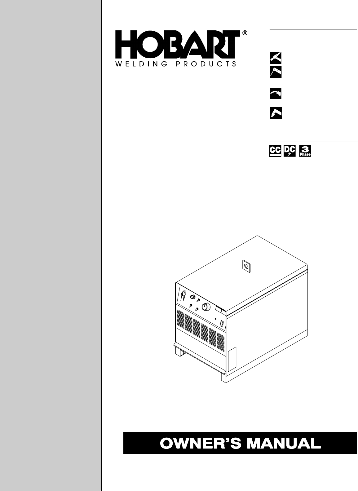
OM-222 164 850T January 2002 Processes TIG (GTAW) Welding Stick (SMAW) Welding Flux Cored (FCAW) Welding Air Plasma Cutting and Gouging Air Carbon Arc (CAC-A) Cutting and Gouging Description Arc Welding Power Source Cyber Arc 302, 452, And 652 Models
From Hobart to You Thank you and congratulations on choosing Hobart. Now you can get the job done and get it done right. We know you don’t have time to do it any other way. This Owner’s Manual is designed to help you get the most out of your Hobart products. Please take time to read the Safety precautions. They will help you protect yourself against potential hazards on the worksite. We’ve made installation and operation quick and easy.
TABLE OF CONTENTS The following terms are used interchangeably throughout this manual: TIG = GTAW Stick = SMAW WARNING This product, when used for welding or cutting, produces fumes or gases which contain chemicals known to the State of California to cause birth defects and, in some cases, cancer. (California Health & Safety Code Section 25249.5 et seq.) SECTION 1 – SAFETY PRECAUTIONS . . . . . . . . . . . . . . . . . . . . . . . . . . . . . . . . . . . . . . . . . . . . . . . . . . 1-1. Symbol Usage . .
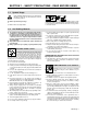
SECTION 1 – SAFETY PRECAUTIONS - READ BEFORE USING som _nd_4/98 1-1. Symbol Usage Means Warning! Watch Out! There are possible hazards with this procedure! The possible hazards are shown in the adjoining symbols. Y Marks a special safety message. . Means “Note”; not safety related. This group of symbols means Warning! Watch Out! possible ELECTRIC SHOCK, MOVING PARTS, and HOT PARTS hazards. Consult symbols and related instructions below for necessary actions to avoid the hazards. 1-2.
ARC RAYS can burn eyes and skin. Arc rays from the welding process produce intense visible and invisible (ultraviolet and infrared) rays that can burn eyes and skin. Sparks fly off from the weld. D Wear a welding helmet fitted with a proper shade of filter to protect your face and eyes when welding or watching (see ANSI Z49.1 and Z87.1 listed in Safety Standards). D Wear approved safety glasses with side shields under your helmet.
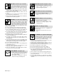
1-3. Additional Symbols For Installation, Operation, And Maintenance FIRE OR EXPLOSION hazard. MOVING PARTS can cause injury. D Do not install or place unit on, over, or near combustible surfaces. D Do not install unit near flammables. D Do not overload building wiring – be sure power supply system is properly sized, rated, and protected to handle this unit. D Keep away from moving parts such as fans. D Keep all doors, panels, covers, and guards closed and securely in place.
1-5. EMF Information Considerations About Welding And The Effects Of Low Frequency Electric And Magnetic Fields Welding current, as it flows through welding cables, will cause electromagnetic fields. There has been and still is some concern about such fields.
SECTION 1 – CONSIGNES DE SECURITE – LIRE AVANT UTILISATION som _nd_fre 4/98 1-1. Signification des symboles Signifie Mise en garde ! Soyez vigilant ! Cette procédure présente des risques de danger ! Ceux-ci sont identifiés par des symboles adjacents aux directives. Y Identifie un message de sécurité particulier. . Signifie NOTA ; n’est pas relatif à la sécurité.
LES RAYONS DE L’ARC peuvent provoquer des brûlures dans les yeux et sur la peau. Le rayonnement de l’arc du procédé de soudage génère des rayons visibles et invisibles intenses (ultraviolets et infrarouges) susceptibles de provoquer des brûlures dans les yeux et sur la peau. Des étincelles sont projetées pendant le soudage. D Porter un casque de soudage muni d’un écran de filtre approprié pour protéger votre visage et vos yeux pendant le soudage ou pour regarder (voir ANSI Z49.1 et Z87.
1-3. Dangers supplémentaires en relation avec l’installation, le fonctionnement et la maintenance Risque D’INCENDIE OU D’EXPLOSION. DES ORGANES MOBILES peuvent provoquer des blessures. D Ne pas placer l’appareil sur, au-dessus ou à proximité de surfaces infllammables. D Rester à l’écart des organes mobiles comme le ventilateur. D Maintenir fermés et fixement en place les portes, panneaux, recouvrements et dispositifs de protection.
1-4. Principales normes de sécurité Safety in Welding and Cutting, norme ANSI Z49.1, de l’American Welding Society, 550 N.W. Lejeune Rd, Miami FL 33126 Safety and Health Sandards, OSHA 29 CFR 1910, du Superintendent of Documents, U.S. Government Printing Office, Washington, D.C. 20402. Recommended Safe Practice for the Preparation for Welding and Cutting of Containers That Have Held Hazardous Substances, norme AWS F4.1, de l’American Welding Society, 550 N.W.
SECTION 2 – DEFINITIONS 2-1. General Precautionary Label Warning! Watch Out! There are possible hazards as shown by the symbols. 1 1.1 1.2 1.3 2 2.1 2.2 2.3 3 3.1 3.2 3.3 4 4.1 5 6 Electric shock from welding electrode or wiring can kill. Wear dry insulating gloves. Do not touch electrode with bare hand. Do not wear wet or damaged gloves. Protect yourself from electric shock by insulating yourself from work and ground. Disconnect input plug or power before working on machine.
2-2. Input Connection Label 1 2 3 4 1 Warning! Watch Out! There are possible hazards as shown by the symbols. Electric shock from wiring can kill. Disconnect input plug or power before working on machine. Read the Owner’s Manual before working on this machine. Consult rating label for input power requirements, and check power available at the job site – they must match. Read Owner’s Manual and inside labels for connection points and procedures.
2-5. Manufacturer’s Rating Labels For CE Products . Match label to one on unit. See Section 3-4.
2-6. Symbols And Definitions Note Some symbols are found only on CE products.
SECTION 3 – INSTALLATION 3-1. Specifications Maximum OpenCircuit Voltage DC IP Rating 15 – 395 72 (70) 450 A @ 38 Volts DC, 60% Duty Cycle 20 – 590 650 A @ 44 Volts DC, 60% Duty Cycle 50 – 850 Rated Welding Output Amp Range DC 300 Amp 300 A @ 32 Volts DC, 60% Duty Cycle 450 Amp 650 Amp Model Amperes Input at Rated Load Output, 50 or 60 Hz, Three-Phase 200 V 230 V 380 V 400 V 440 V 460 V 575 V KVA KW 21M 70 4.0* 61 3.6* 35 1.1* 33 1.1* 31 1.0* 31 3.1* 25 1.5* 24.5 1.3* 13.
3-3. Volt-Ampere Curves A. 300 Amp Model Volt-ampere curves show minimum and maximum voltage and amperage output capabilities of unit. Curves of other settings fall between curves shown. B. 450 Amp Model C.
3-4. Selecting A Location 1 2 Lifting Eye Lifting Forks Use lifting eye or lifting forks to move unit. If using lifting forks, extend forks beyond opposite side of unit. Movement 3 1 Rating Label (Non CE Models Only) Use rating label to determine input power needs. Label located under front access door. 4 OR 2 5 Location And Airflow Plate Label (CE Models Only) Label located under front access door. Rating Label (CE Models Only) Use rating label to determine input power needs.
3-6. Tipping Y Be careful when placing or moving unit over uneven surfaces. 3-7. 115 VAC Receptacle And Circuit Breakers Y Turn Off power before connecting to receptacle. 1 115 V 15 A AC Receptacle RC9 Power is shared between RC9 and Remote 14 receptacle RC8 (see Section 3-10). 3 2 3 2 CB1 protects the 115 volts ac portion of RC8 and RC9 from overload. 1 Circuit Breaker CB1 Circuit Breaker CB2 CB2 protects the 24 volts ac portion of RC8 and Remote Power On/Off from overload.
3-8.
3-10. Connecting Remote Control 1 Remote 14 Receptacle RC8 Connect remote control to RC8. 1 A B K J I H C L N D M G E F OR OR Ref.
3-11.
3-12. Placing Jumper Links Y Disconnect and lockout/tagout input power before installing or moving jumper links. Check input voltage available at site. 1 Jumper Link Label Check label – only one is on unit. 2 Jumper Links Move jumper links to match input voltage. Close access door, or go on to Section 3-13. 200 VOLTS 230 VOLTS 460 VOLTS Ref. S-174 976-A 230 VOLTS 460 VOLTS 575 VOLTS Ref. S-174 973-A 1 220 VOLTS 380 VOLTS 400 VOLTS 440 VOLTS (FACTORY OPTION) Ref.
3-13. Connecting Input Power Y Disconnect and lockout/tagout input power before connecting input conductors from unit. Y Have only qualified persons make this installation. See rating label on unit and check input voltage available at site. = GND/PE Earth Ground 1 2 3 Line Disconnect Device Input Conductors Grounding Conductor 1 Select size and length using Section 3-11. Conductors must comply with national, state, and local electrical codes.
SECTION 4 – OPERATION 4-1. Controls (Non CE Models) 300 Amp Model Shown 1 2 9 3 8 5 4 7 6 Ref. ST-165 596-D short arc length without sticking the electrode. 1 Polarity Selector Switch (Optional On 50 Hz Models) To change polarity on models not equipped with a Polarity Selector switch, reverse work and electrode cables at the weld output terminals (see Section 3-8). Y Turn Off Power before reversing cables.
4-2. Controls (CE Models) 300 Amp Model Shown 2 1 9 3 4 5 8 7 6 Ref. ST-173 450-B short arc length without sticking the electrode. 1 Polarity Selector Switch (Optional On 50 Hz Models) To change polarity on models not equipped with a Polarity Selector switch, reverse work and electrode cables at the weld output terminals (see Section 3-8). Y Turn Off Power before reversing cables.
5-2. Fuse F1 Y Turn Off power before opening rear access door. 1 Fuse F1 (See Parts List For Rating) Fuse F1 protects control transformer from overload. If F1 opens, weld output and fan motor stops. Replace F1. 1 Tools Needed: 3/8 in Ref. ST-800 101-C 5-3. Troubleshooting Trouble No weld output; unit completely inoperative. Remedy Place line disconnect switch in On position (see Section 3-13). Check fuse F1, and replace if necessary (see Section 5-2).
SECTION 6 – ELECTRICAL DIAGRAM For Primary Circuit Diagram Portion, refer to Circuit Diagram located inside wrapper of welding power source. SC-203 802 Figure 6-1.
SECTION 7 – PARTS LIST 22 . Hardware is common and 21 29 (Fig.7–3 & 4) 22 1 28 (Fig.7–2) 27 3 2 4 24 26 25 5 23 6 8 7 11 10 4 13 12 15 9 14 16 17 3 19 20 18 (Fig.7–5) not available unless listed. Figure 7-1.
Item No. Dia. Mkgs. Part No. Description Quantity Model 302 452 652 Figure 7-1. Main Assembly . . . 1 . . . . . . . . . . . . +179 430 . . . 1 . . . . . . . . . . . . +179 432 . . . 2 . . . . . . . . . . . . . 179 429 . . . 2 . . . . . . . . . . . . . 179 431 . . . 3 . . . . . . . . . . . . . 164 699 . . . 3 . . . . . . . . . . . . . 164 700 . . . 4 . . . . . . . . . . . . . 162 816 . . . 5 . . . . . . . . . . . . . 162 820 . . . 6 . . . . . . . . . . . . . 162 830 . . . 7 . . . . . . . . . . . . .
Item No. Dia. Mkgs. Part No. Description Quantity Model 302 452 652 Figure 7-1. Main Assembly (Continued) . . . 24 . . . . . T1 . . . . 189 855 . . . 25 . . . . . . . . . . . . . 172 410 . . . 26 . . . . . . . . . . . . . 172 409 . . . 24 . . . . . T1 . . . . 189 858 . . . 25 . . . . . . . . . . . . . 172 416 . . . 26 . . . . . . . . . . . . . 172 415 . . . . . . . . . TP1,2 . . . 119 581 . . . . . . . . . TP4,5 . . . 168 891 . . . . . . . . . PLG13 . . 189 873 . . . . . . . . . PLG6 . . . 168 847 . .
Item No. Dia. Mkgs. Part No. Description Quantity Model 302 452 652 Figure 7-2. Panel, Front w/Components (Fig 7-1 Item 28) . . . 1 . . . . . S5 . . ♦169 331 . . . 1 . . . . . S5 . . ♦169 332 . . . 2 . . . . PC1 . . . . 187 822 . . . 2 . . . . PC1 . . . . 186 937 . . . 2 . . . . PC1 . . . . 187 825 . . . 2 . . . . PC1 . . . . 187 823 . . . 2 . . . . PC1 . . . . 187 824 . . . 2 . . . . PC1 . . . . 187 826 . . . . . . . . . PLG1 . . . 158 720 . . . . . . . . . PLG3 . . . 169 240 . . . . . . . . . PLG5 .
Item No. Dia. Mkgs. Part No. Description Quantity Model 302 452 652 Figure 7-2. Panel, Front w/Components (Fig 7-1 Item 28) (Continued) . . . 9 . . . . POS . . . 181 245 . . TERMINAL, pwr output red . . . . . . . . . . . . . . . . . . . . . . . . . . . . . . . . 10 . . . . C4,5 . . . 128 750 . . CAPACITOR, cer disc .1uf 500VDC . . . . . . . . . . . . . . . . . . . . . . . . . 11 . . . . . . . . . . . . . 161 303 . . SPRING, cprsn .600 OD x .072 wire x 1.500 lg . . . . . . . . . . . . . . . 12 . . . .
Item No. Dia. Mkgs. Part No. SR1 175 070 . . . 1 . . . . C7-12 . . . . ... 2 ............... ... 3 ............... ... 4 ............... . . . 5 . . . . . TP3 . . . . . . . . 6 . . . . . TP6 . . . . . . . . 7 . . . SCR1-6 . . . . . . . . . . . . . PLG1 . . . . ... 8 ............... Description Quantity Figure 7-3. Rectifier, Si Diode (302 Model) (Fig 7-1 Item 29) 048 420 177 316 177 317 166 667 185 679 185 680 161 668 158 720 188 692 .. .. .. .. .. .. .. .. .. 3 CAPACITOR, cer disc .
Item No. Dia. Mkgs. Part No. Description Quantity Figure 7-5. Panel, Rear w/Components (Fig 7-1 Item 18) . . . 1 . . . . . . . . . . . . . . . 173 283 . . . 2 . . . . . . . . . . . . . . . 180 165 . . . 3 . . . . . . . . . . . . . . . 162 807 . . . 4 . . . . . . . . . . . . . . . 168 343 . . . 5 . . . . . . . . . . . . . . +162 818 . . . 6 . . . . . . . . . . . . . . . 168 384 . . . 7 . . . . . . . . . . . . . . . 602 177 . . . 8 . . . . . . . . . . . . . . . 124 274 . . . 9 . . . . . R3 . . . . . .
Effective January 1, 2001 (Equipment with a serial number preface of “LB” or newer) This limited warranty supersedes all previous Hobart warranties and is exclusive with no other guarantees or warranties expressed or implied. Warranty Questions? Call 1-877-HOBART1 for your local Hobart distributor. Service You always get the fast, reliable response you need. Most replacement parts can be in your hands in 24 hours.
Owner’s Record Please complete and retain with your personal records. Model Name Serial/Style Number Purchase Date (Date which equipment was delivered to original customer.) Distributor Address City State Zip Resources Available Always provide Model Name and Serial/Style Number. To locate a Distributor, retail or service location: Contact your Distributor for: Welding Supplies and Consumables Call 1-877-Hobart1 or visit our website at www.HobartWelders.