OM-314 029 861V November 1999 Processes Stick (SMAW) Welding Description Arc Welding Power Source Cyberstick 250 AC/DC
From Hobart to You Thank you and congratulations on choosing Hobart. Now you can get the job done and get it done right. We know you don’t have time to do it any other way. This Owner’s Manual is designed to help you get the most out of your Hobart products. Please take time to read the Safety precautions. They will help you protect yourself against potential hazards on the worksite. We’ve made installation and operation quick and easy.
TABLE OF CONTENTS The following terms are used interchangeably throughout this manual: TIG = GTAW Stick = SMAW WARNING This product, when used for welding or cutting, produces fumes or gases which contain chemicals known to the State of California to cause birth defects and, in some cases, cancer. (California Health & Safety Code Section 25249.5 et seq.) OM-314V SECTION 1 – SAFETY PRECAUTIONS - READ BEFORE USING . . . . . . . . . . . . . . . . . . . . . . . . . . . . 1-1. Symbol Usage . . . . . . . . . .
SECTION 1 – SAFETY PRECAUTIONS - READ BEFORE USING som _nd_4/98 1-1. Symbol Usage Means Warning! Watch Out! There are possible hazards with this procedure! The possible hazards are shown in the adjoining symbols. Y Marks a special safety message. . Means “Note”; not safety related. This group of symbols means Warning! Watch Out! possible ELECTRIC SHOCK, MOVING PARTS, and HOT PARTS hazards. Consult symbols and related instructions below for necessary actions to avoid the hazards. 1-2.
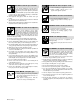
ARC RAYS can burn eyes and skin. Arc rays from the welding process produce intense visible and invisible (ultraviolet and infrared) rays that can burn eyes and skin. Sparks fly off from the weld. D Wear a welding helmet fitted with a proper shade of filter to protect your face and eyes when welding or watching (see ANSI Z49.1 and Z87.1 listed in Safety Standards). D Wear approved safety glasses with side shields under your helmet.
1-3. Additional Symbols For Installation, Operation, And Maintenance FIRE OR EXPLOSION hazard. MOVING PARTS can cause injury. D Do not install or place unit on, over, or near combustible surfaces. D Do not install unit near flammables. D Do not overload building wiring – be sure power supply system is properly sized, rated, and protected to handle this unit. D Keep away from moving parts such as fans. D Keep all doors, panels, covers, and guards closed and securely in place.
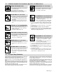
1-5. EMF Information Considerations About Welding And The Effects Of Low Frequency Electric And Magnetic Fields Welding current, as it flows through welding cables, will cause electromagnetic fields. There has been and still is some concern about such fields.
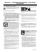
SECTION 1 – CONSIGNES DE SECURITE – LIRE AVANT UTILISATION som _nd_fre 4/98 1-1. Signification des symboles Signifie Mise en garde ! Soyez vigilant ! Cette procédure présente des risques de danger ! Ceux-ci sont identifiés par des symboles adjacents aux directives. Y Identifie un message de sécurité particulier. . Signifie NOTA ; n’est pas relatif à la sécurité.
LES RAYONS DE L’ARC peuvent provoquer des brûlures dans les yeux et sur la peau. Le rayonnement de l’arc du procédé de soudage génère des rayons visibles et invisibles intenses (ultraviolets et infrarouges) susceptibles de provoquer des brûlures dans les yeux et sur la peau. Des étincelles sont projetées pendant le soudage. D Porter un casque de soudage muni d’un écran de filtre approprié pour protéger votre visage et vos yeux pendant le soudage ou pour regarder (voir ANSI Z49.1 et Z87.
1-3. Dangers supplémentaires en relation avec l’installation, le fonctionnement et la maintenance Risque D’INCENDIE OU D’EXPLOSION. DES ORGANES MOBILES peuvent provoquer des blessures. D Ne pas placer l’appareil sur, au-dessus ou à proximité de surfaces infllammables. D Rester à l’écart des organes mobiles comme le ventilateur. D Maintenir fermés et fixement en place les portes, panneaux, recouvrements et dispositifs de protection.
1-4. Principales normes de sécurité Safety in Welding and Cutting, norme ANSI Z49.1, de l’American Welding Society, 550 N.W. Lejeune Rd, Miami FL 33126 Safety and Health Sandards, OSHA 29 CFR 1910, du Superintendent of Documents, U.S. Government Printing Office, Washington, D.C. 20402. Recommended Safe Practice for the Preparation for Welding and Cutting of Containers That Have Held Hazardous Substances, norme AWS F4.1, de l’American Welding Society, 550 N.W.
SECTION 2 – INSTALLATION 2-1. Specifications Model Amperes Input At Rated Load Output, 50 Hz, Single-Phase Amperes Input At Rated Load Output, 60 Hz, Single-Phase 220 V 260 V 380 V 440 V 520 V KVA KW 200 V 230 V 460 V 575 V KVA KW AC 68 57.5 39.3 34 28.7 14.9 11 78 68 34 27 15.6 11.8 DC 52 44 30 26 22 11.4 8 57 50 25 20 11.5 8.2 (21.3) (16.0) (12.2) (10.5) (8.2) (4.5) (0.5) (25) (21.8) (11) (8.9) (5.0) (0.45) AC 84 -- 48.6 42 -- 18.
2-3. Volt-Ampere Curves The volt-ampere curves show the minimum and maximum voltage and amperage output capabilities of the welding power source. Curves of other settings fall between the curves shown. A. DC Mode B. AC Mode ssb1.1 10/91 – SB-002 696-A / SB–002 689-A 2-4.
2-5. Selecting A Location 1 Rating Label Use rating label to determine input power needs. Label located on front panel. Movement Tipping 2 Y Do not move or operate unit where it could tip. Line Disconnect Device Locate unit near correct input power supply. Y Special installation may be required where gasoline or volatile liquids are present – see NEC Article 511 or CEC Section 20. Location And Airflow 2 1 18 in (460 mm) 18 in (460 mm) loc_1 3/96 / Ref. ST-111 900-D 2-6.
2-7. Connecting To Weld Output Terminals For DC Weld Output 1 2 1 Negative (–) Weld Output Terminal Positive (+) Weld Output Terminal For Electrode Positive (DCEP), connect work cable to Negative (–) terminal and electrode holder cable to Positive (+) terminal. 2 For Electrode Negative (DCEN), reverse cable connections. For AC Weld Output 3 4 3 4 Work Weld Output Terminal Electrode Weld Output Terminal Connect work cable to Work terminal and electrode cable to Electrode terminal. Close access door.
2-8.
2-9. Placing Jumper Links And Connecting Input Power Y Have only qualified persons make this installation. See rating label in Section 2-5, and be sure to supply correct input power. L1 Check input voltage available at site. L2 Remove side panel. 1 Jumper Link Label Check label – only one is on unit. Move jumper links to match input voltage, and label on unit. 2 Input And Grounding Conductors See Section 2-8. 3 Line Disconnect Device See Section 2-8. Connect input power. Reinstall side panel.
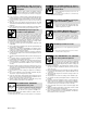
SECTION 3 – OPERATION 3-1. Controls 2 1 3 4 ST-186 137 1 Range Selector Switch Use switch to select ac or dc weld amperage range. If desired amperage is in the overlapping area of two ranges, set switch in the lower range for better fine amperage control. Y Do not change position of switch while welding. 2 Amperage Adjustment Control Use control to adjust amperage within range selected by Range Selector switch.
SECTION 4 – MAINTENANCE & TROUBLESHOOTING 4-1. Routine Maintenance . Maintain more often Y Disconnect power before maintaining. during severe conditions. 3 Months Repair Or Replace Cracked Weld Cable Replace Unreadable Labels 3 Months 6 Months Clean And Tighten Weld Terminals Blow Out Or Vacuum Inside OR During Heavy Service, Clean Monthly 4-2. Troubleshooting Trouble No weld output. Remedy Place Power switch in the On position (see Section 3-1).
SECTION 5 – ELECTRICAL DIAGRAMS For Primary Circuit Diagram Portion, refer to the Circuit Diagram located inside the wrapper of the welding power source. SB-090 666-D Figure 5-1. Circuit Diagram For 60 Hertz Models For Primary Circuit Diagram Portion, refer to the Circuit Diagram located inside the wrapper of the welding power source. SB-090 667-D Figure 5-2.
SECTION 6 – PARTS LIST . Hardware is common and not available unless listed. 1 8 9 2 7 10 3 11 6 6 5 12 4 17 15 14 13 FIG 6–4 16 FIG 6–2 ST-133 712-G Figure 6-1.
Replace Coils at Factory or Factory Authorized Service Station Quantity Item No. Dia. Mkgs. Part No. Description Model Without With PFC PFC Figure 6-1. Main Assembly . . 1 . . . . . . . . . . . . 034 288 . . 2 . . . . . . . . . . . . 109 035 . . 3 . . . . . . . . . . + 161 408 . . 4 . . . . C1 . . . . 114 543 . . 5 . . . . . . . . . . . . 025 141 . . 6 . . . . . . . . . . . . 092 614 . . 7 . . . . Z1 . . . . 161 444 . . 8 . . . MA1 . . . 088 097 . . 8 . . . MA1 . . . 088 921 . . 9 . . . . . . . . . . .
Item No. Dia. Mkgs. Part No. Description Quantity Figure 6-2. Panel, Front w/Components (Fig 6-1 Item 16) ... ... ... ... ... ... ... ... ... ... ... ... ... ... 1 2 3 4 5 6 7 8 9 10 11 12 13 14 .......................... . . . . . . . . . . . . . . +186 131 . . . . . . . S2 . . . . . . 088 087 . . . . . . . R2 . . . . . . 083 671 . . . . . . CB1 . . . . . 083 432 . . . . . . . S1 . . . . . . 045 834 . . . Elect,Work . . 099 255 . . . . . . . Pos . . . . . 039 047 . . . . . . Neg . . . . . 039 046 .
Item No. Part No. Description 088 087 ..... ..... ..... ..... ..... ..... ..... ..... ..... ..... ..... 1 ......... 2 ......... 3 ......... 4 ......... 5 ......... 6 ......... 7 ......... 8 ......... 9 ......... 10 . . . . . . . . 11 . . . . . . . . . 072 026 164 169 072 028 011 644 011 645 011 075 011 953 011 074 072 082 072 027 005 558 Quantity Figure 6-3. Switch, Range 2 Position (Fig 6-2 Item 3) . . BRACKET, mtg switch . . . . . . . . . . . . . . . . . . . . . . . . . . . . . . . . . . . . . . .
Notes OM-314 Page 22
Effective October 1, 1999 Warranty Questions? Call 1-877-HOBART1 for your local Hobart distributor. Service You always get the fast, reliable response you need. Most replacement parts can be in your hands in 24 hours. Support Need fast answers to the tough welding questions? Contact your distributor or call 1-800-332-3281. The expertise of the distributor and Hobart is there to help you, every step of the way.
Owner’s Record Please complete and retain with your personal records. Model Name Serial/Style Number Purchase Date (Date which equipment was delivered to original customer.) Distributor Address City State Zip Resources Available Always provide Model Name and Serial/Style Number. To locate a Distributor, retail or service location: Contact your Distributor for: Welding Supplies and Consumables Call 1-877-Hobart1 or visit our website at www.HobartWelders.