OM-356 188694J October 2000 Processes TIG (GTAW) Welding Stick (SMAW) Welding Description Arc Welding Power Source CYBERTIG 350LX And Non-CE Models Visit our website at www.HobartWelders.
From Hobart to You Thank you and congratulations on choosing Hobart. Now you can get the job done and get it done right. We know you don’t have time to do it any other way. This Owner’s Manual is designed to help you get the most out of your Hobart products. Please take time to read the Safety precautions. They will help you protect yourself against potential hazards on the worksite. We’ve made installation and operation quick and easy.
TABLE OF CONTENTS The following terms are used interchangeably throughout this manual: TIG = GTAW Stick = SMAW WARNING This product, when used for welding or cutting, produces fumes or gases which contain chemicals known to the State of California to cause birth defects and, in some cases, cancer. (California Health & Safety Code Section 25249.5 et seq.) SECTION 1 – SAFETY PRECAUTIONS - READ BEFORE USING . . . . . . . . . . . . . . . . . . . . . . . . . . . . 1-1. Symbol Usage . . . . . . . . . . . . . .
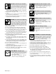
SECTION 1 – SAFETY PRECAUTIONS - READ BEFORE USING som _nd_4/98 1-1. Symbol Usage Means Warning! Watch Out! There are possible hazards with this procedure! The possible hazards are shown in the adjoining symbols. Y Marks a special safety message. . Means “Note”; not safety related. This group of symbols means Warning! Watch Out! possible ELECTRIC SHOCK, MOVING PARTS, and HOT PARTS hazards. Consult symbols and related instructions below for necessary actions to avoid the hazards. 1-2.
ARC RAYS can burn eyes and skin. Arc rays from the welding process produce intense visible and invisible (ultraviolet and infrared) rays that can burn eyes and skin. Sparks fly off from the weld. D Wear a welding helmet fitted with a proper shade of filter to protect your face and eyes when welding or watching (see ANSI Z49.1 and Z87.1 listed in Safety Standards). D Wear approved safety glasses with side shields under your helmet.
1-3. Additional Symbols For Installation, Operation, And Maintenance FIRE OR EXPLOSION hazard. MOVING PARTS can cause injury. D Do not install or place unit on, over, or near combustible surfaces. D Do not install unit near flammables. D Do not overload building wiring – be sure power supply system is properly sized, rated, and protected to handle this unit. D Keep away from moving parts such as fans. D Keep all doors, panels, covers, and guards closed and securely in place.
1-5. EMF Information Considerations About Welding And The Effects Of Low Frequency Electric And Magnetic Fields Welding current, as it flows through welding cables, will cause electromagnetic fields. There has been and still is some concern about such fields.
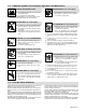
SECTION 1 – CONSIGNES DE SECURITE – LIRE AVANT UTILISATION som _nd_fre 4/98 1-1. Signification des symboles Signifie Mise en garde ! Soyez vigilant ! Cette procédure présente des risques de danger ! Ceux-ci sont identifiés par des symboles adjacents aux directives. Y Identifie un message de sécurité particulier. . Signifie NOTA ; n’est pas relatif à la sécurité.
LES RAYONS DE L’ARC peuvent provoquer des brûlures dans les yeux et sur la peau. Le rayonnement de l’arc du procédé de soudage génère des rayons visibles et invisibles intenses (ultraviolets et infrarouges) susceptibles de provoquer des brûlures dans les yeux et sur la peau. Des étincelles sont projetées pendant le soudage. D Porter un casque de soudage muni d’un écran de filtre approprié pour protéger votre visage et vos yeux pendant le soudage ou pour regarder (voir ANSI Z49.1 et Z87.
1-3. Dangers supplémentaires en relation avec l’installation, le fonctionnement et la maintenance Risque D’INCENDIE OU D’EXPLOSION. DES ORGANES MOBILES peuvent provoquer des blessures. D Ne pas placer l’appareil sur, au-dessus ou à proximité de surfaces infllammables. D Rester à l’écart des organes mobiles comme le ventilateur. D Maintenir fermés et fixement en place les portes, panneaux, recouvrements et dispositifs de protection.
1-4. Principales normes de sécurité Safety in Welding and Cutting, norme ANSI Z49.1, de l’American Welding Society, 550 N.W. Lejeune Rd, Miami FL 33126 Safety and Health Sandards, OSHA 29 CFR 1910, du Superintendent of Documents, U.S. Government Printing Office, Washington, D.C. 20402. Recommended Safe Practice for the Preparation for Welding and Cutting of Containers That Have Held Hazardous Substances, norme AWS F4.1, de l’American Welding Society, 550 N.W.
SECTION 2 – DEFINITIONS 2-1. Warning Label Definitions Warning! Watch Out! There are possible hazards as shown by the symbols. 1 1.1 1.2 1.3 2 1 1.1 2.1 1.3 1.2 2.2 2.3 3 2 2.1 2.2 3.1 2.3 3.2 3 3.1 3.2 3.3 3.3 4 4.1 4 4.1 + + 5 + 6 5 Electric shock from welding electrode or wiring can kill. Wear dry insulating gloves. Do not touch electrode with bare hand. Do not wear wet or damaged gloves. Protect yourself from electric shock by insulating yourself from work and ground.
2-2.
2-3. Symbols And Definitions NOTE A V Some symbols are found only on CE products.
SECTION 3 – INSTALLATION 3-1. Selecting A Location Y Falling Injury. S Movement S 1 S OR 2 1 2 Unit Can Cause Use lifting eye to lift unit only, NOT running gear, gas cylinders, or any other accessories. Use equipment of adequate capacity to lift and support unit. If using lift forks to move unit, be sure forks are long enough to extend beyond opposite side of unit. Lifting Eye Lifting Forks Use lifting eye or lifting forks to move unit.
3-2. Dimensions And Weights Dimensions A B Height 38-1/4 in (972 mm) with retractable lifting eye down Width 22-1/2 in (572 mm) Length 25 in (635 mm) A 25 in (635 mm) B 23-5/8 in (600 mm) C 1-3/8 in (35 mm) D 7/8 in (22 mm) E 19-15/16 (506 mm) F 22-1/4 (565 mm) G 1/2 in (13 mm) Dia D C E Front F Weight Ref. ST-184 046 G 4 Holes 515 lbs (234 kg) 3-3.
3-4. Duty Cycle And Overheating Duty Cycle is the percentage of 10 minutes that the unit can weld at rated load without overheating. If unit overheats, output stops, front panel voltmeter/ammeter displays a HLP3 or HLP5 message (see Section 5-4), and cooling fans run. Wait fifteen minutes for unit to cool. Reduce amperage or duty cycle before welding. Y Exceeding duty cycle can damage unit and void warranty.
3-6. Weld Output Terminals And Selecting Cable Sizes Y ARC WELDING can cause Electromagnetic Interference. To reduce possible interference, keep weld cables as short as possible, close together, and down low, such as on the floor. Locate welding operation 100 meters from any sensitive electronic equipment. Be sure this welding machine is installed and grounded according to this manual.
3-8. Shielding Gas Connections And 115 Volts AC Duplex Receptacle Y Turn Off power before connecting to receptacle. 1 Gas Valve In Fitting Located on rear of unit. 2 4 Gas Valve Out Fitting Fittings have 5/8-18 right-hand threads. 3 5 3 Cylinder Valve Open valve slightly so gas flow blows dirt from valve. Close valve. 4 Regulator/Flow Gauge Connect regulator/flow gauge to gas cylinder. Connect customer supplied gas hose between regulator/flow gauge and gas in fitting.
3-9. Electrical Service Guide NOTE All values calculated at 60% duty cycle.
3-10. Placing Jumper Links And Connecting Input Power Check input voltage available at site. 1 Jumper Link Label Check label – only one is on unit. 200 VOLTS 230 VOLTS 460 VOLTS 2 Jumper Links Move jumper links to match input voltage. L L L L L L 3 S-083 566-C 2 230 VOLTS 460 VOLTS Select size and length using Section 3-9. 575 VOLTS 4 L L L L L Input And Grounding Conductors Line Disconnect Device Select type and size of overcurrent protection using Section 3-9.
SECTION 4 – OPERATION 4-1. Controls A. For 200/230/460 Volts And Non CE Units 1 2 3 4 6 5 7 13 14 15 16 11 17 12 10 9 8 18 . Top row of lights in upper left corner are 1 On for SMAW. Bottom row are On for GTAW. Process Control See Section 4-7 See Section 4-9. 7 Pulse Controls: Amperage Adjustment Control See Section 4-8. See Section 4-3. 8 2 See Section 4-2. Current Control See Section 4-4. 3 Output Control See Section 4-5. 4 Start Mode Button See Section 4-6.
B. For CE Units 1 2 3 4 6 5 7 13 14 15 16 11 17 12 10 9 8 18 . Top row of lights in upper left corner are 1 On for SMAW. Bottom row are On for GTAW. Process Control See Section 4-7 See Section 4-9. 7 Pulse Controls: Amperage Adjustment Control See Section 4-8. See Section 4-3. 8 2 See Section 4-2. Current Control See Section 4-4. 3 Output Control See Section 4-5. 4 Start Mode Button See Section 4-6.
4-2. Output Selector Switch 1 (CE Nameplate Shown) 1 Output Selector Switch Y Do not use AC output in damp areas, if movement is confined, or if there is danger of falling. Use AC output ONLY if required for the welding process, and then use a remote control. Y Do not change position of switch while welding or while under load. Use switch to select (DCEN) Direct Current Electrode Negative, AC, or (DCEP) Direct Current Electrode Positive output without changing weld output cable connections.
4-4. Current Control 1 (CE Nameplate Only) 1 1 Current Control Use control to select front panel or remote current control. For front panel current control, press button to toggle LED to Panel position. For remote current control, press button to toggle LED to Remote 14 position (see Section 3-7). NOTE: Lit LED indicates selected mode. When Output Selector switch position changes, LED may change position, based upon last selection. 4-5.
4-6. Start Mode (CE Nameplate Only) 1 1 2 3 Lift-Arct Start Method “Touch” 1–2 Seconds Do NOT Strike Like A Match! 1 Start Mode For SMAW welding, press button to toggle LED to Off position. For GTAW welding, use control to select Off for no HF, Lift-Arct, HF for arc starting only, or continuous HF. See Section 4-13 for adjusting high frequency intensity. Application: When Off is selected, use the scratch method to start an arc for both the SMAW and GTAW processes. and slowly lift electrode.
4-7. Meters 1 Voltmeter Voltmeter displays average voltage (to the nearest 0.1 V) at the weld output terminals. 1 2 Ammeter Use meter to preset amperage. Meter displays average weld amperage output of unit to nearest ampere when welding. 2 4-8. Amperage Adjustment Control 1 (CE Nameplate Only) 1 1 Amperage Adjustment Control Use control to adjust amperage, and preset amperage on ammeter (see Section 4-7). This control may be adjusted while welding.
4-9. Balance/DIG Control (CE Nameplate Only) 1 1 1 Balance/DIG Control Balance Control (AC GTAW): Control changes the AC output square wave. Rotating the control towards 10 provides deeper penetration. Rotating the control towards 0 provides more cleaning action of the workpiece. When the control is in the Balanced position, the wave shape provides equal penetration and cleaning action.
4-11. Postflow Time Control 1 (CE Nameplate Only) 1 1 Postflow Time Control Use control to set length of time (0–50 seconds) gas flows after welding stops. It is important to set enough time to allow gas to flow until after the tungsten and weld puddle has cooled down. Application: Postflow is required to cool tungsten and weld, and to prevent contamination of tungsten and weld. Increase postflow time if tungsten or weld are dark in appearance.
4-12. Setting Pulse Controls 1 1 2 3 4 On/Off Switch Use switch to turn pulse function On and Off. 2 Background Amps Use Background Amps control to set the low pulse of the weld amperage, which cools the weld puddle and affects overall heat input. Background Amps is set as a percentage of peak amperage. 3 (CE Nameplate Only) 1 2 3 4 Pulse Frequency A range from 0.25–10.0 pps (pulses per second). Control is used to determine appearance of weld bead.
4-13. High Frequency Control 1 Y Do not use high frequency while Shielded Metal Arc Welding (SMAW). 1 Arc rectification can occur when welding above 200 amps and/or while welding with helium gas. If this condition occurs, increasing the HF Intensity control towards maximum, may help to restabilize the arc. High Frequency Control . As high frequency intensity is increased, the possibility of inter- For GTAW, use control to set HF intensity. Set as low as possible.
4-15. Sequence Selection Switch 1 (CE Nameplate Only) 1 Sequence Selection Switch Switch controls Off, Start, Crater, Start/Crater, 4t, and Spot functions. Place switch in desired position. 1 Off– Place switch in Off position when Sequence Selection functions are not desired. 4-16. Start Time/Spot Time Control And Start Current Control 1 (CE Nameplate Only) Sequence Selection Switch Place switch in Start position.
4-17. Crater Time Control And Final Current Control 1 (CE Nameplate Only) 1 1 Sequence Selection Switch Place switch in Crater position. 2 Crater Time Control Use control to reduce current over a set period of time (0–15 seconds) at the end of the weld cycle when NOT using a remote current control. 3 Final Current Control Final current is the current to which weld current has sloped down to (0–100% of current set on Amperage Adjust control).
4-18. Start/Crater Sequence Controls 1 (CE Nameplate Only) 2 1 1 Sequence Selection Switch Place switch in Start/Crater position. Start Time/Spot Time Control Use control to select 0–15 seconds of start time. 3 Start Current Control Use start control to select a starting current (3–400 amps) that is different from the weld current. 4 Crater Time Control Use control to reduce current over a set period of time (0–15 seconds) at the end of the weld cycle when NOT using a remote current control.
4-19. 4T Sequence Selection Controls 1 (CE Nameplate Only) 1 2 1 Start Sequence Switch – 4T Position (Specific trigger method) Press and hold torch trigger to start Preflow Time and arc at the Start Current level. The arc will remain at the Start Current level as long as the trigger is depressed. Release trigger to change to main weld current. To end main weld current, press and hold trigger.
4-20. Spot Time Control 1 (CE Nameplate Only) 1 Sequence Selection Switch – Spot Position Used with the (GTAW) TIG Spot process, generally with a direct current electrode negative (DCEN) setup. 1 2 Start Time/Spot Time Control Use control to select 0–15 seconds of spot time. Use Amperage Adjust control (see Section 4-8) to set amperage. Application: TIG spot welding is used for joining thinner materials that are in close contact, with the fusion method. A good example would be joining coil ends.
SECTION 5 – MAINTENANCE & TROUBLESHOOTING 5-1. Routine Maintenance Y Disconnect power before maintaining. 3 Months Clean And Tighten Weld Terminals Repair Or Replace Cracked Weld Cables Replace Unreadable Labels Adjust Spark Gaps Replace Cracked Parts 14-Pin Cord Torch Cable Gas Hose 6 Months Blow Out Or Vacuum Inside, During Heavy Service, Clean Monthly OR Y Warranty is void if machine fails due to contaminates inside. 5-2.
5-3. Adjusting Spark Gaps Y Turn Off power before adjusting spark gaps. Open access door. 1 4 4 3 2 3 2 Tungsten End Of Point Replace point if tungsten end disappears; do not clean or dress tungsten. 1 Spark Gap Normal spark gap is 0.012 in (0.305 mm). If adjustment is needed, proceed as follows: 3 Adjustment Screws Loosen screws. Place gauge of proper thickness in spark gap. 4 Pressure Point Apply slight pressure at point until gauge is held firmly in gap.
5-4. Voltmeter/Ammeter Help Displays . All directions are in reference to the front of the unit. All circuitry referred to is located inside the unit. 0 Help 0 Display Indicates a short in the thermal protection circuitry located on the transformer of the unit. If this display is shown, contact a Factory Authorized Service Agent. 1 Help 1 Display Not used. 2 Help 2 Display Indicates a malfunction in the thermal protection circuitry located on the transformer of the unit.
5-5. Troubleshooting NOTE: The remedies listed below are recommendations only. If these remedies do not fix the trouble with your unit, have a Factory Authorized Service Agent check unit. There are not user serviceable parts inside unit. Refer to Section 5-4 for any Help (HLP) message displayed on voltmeter/ammeter. Trouble No weld output; unit completely inoperative. Remedy Place line disconnect switch in On position (see Section 3-10). Check and replace line fuse(s), if necessary (see Section 3-10).
Trouble Remedy Check for water in torch, and repair torch if necessary. Fan not operating. OM-356 Page 38 Unit equipped with Fan-On-Demandt. Fans run only when necessary. Unit equipped with circuitry to protect against overheating.
SECTION 6 – ELECTRICAL DIAGRAM SC-187 950-C Figure 6-1.
SECTION 7 – HIGH FREQUENCY 7-1. Welding Processes Requiring High Frequency 1 High-Frequency Voltage TIG – helps arc jump air gap between torch and workpiece and/ or stabilize the arc. 1 Work TIG high_freq 12/96 – S-0693 7-2.
7-3. Correct Installation 7 Weld Zone 3 50 ft (15 m) 50 ft (15 m) 5 1 6 2 8 4 8 Ground all metal objects and all wiring in welding zone using #12 AWG wire. Nonmetal Building Ground workpiece if required by codes. 9 Metal Building 8 8 11 10 Ref. S-0695 / Ref. S-0695 1 High-Frequency Source (welding power source with built-in HF or separate HF unit) Ground metal machine case, work output terminal, line disconnect device, input supply, and worktable.
SECTION 8 – PARTS LIST . Hardware is common and not available unless listed. ST-802 012-F Figure 8-1.
Item No. Dia. Mkgs. Part No. Description Quantity Figure 8-1. Main Assembly . . . 1 . . . . . . . . . . . . . . . . 191 011 . . . 2 . . . . . PC1 . . . . . 196 254 . . . . . . . . . . . . . . . . . . . . . . 186 914 . . . . . . . . PLG13, 15 . . . 131 054 . . . . . . . . . . PLG10 . . . . 165 484 . . . . . . . . . . PLG4 . . . . . 131 055 . . . . . . . . . . PLG14 . . . . 167 333 . . . . . . . . . . . . . . . . . . . . . . 190 512 . . . 3 . . . . . PC2 . . . . . 183 101 . . . 4 . . . . . PC3 . . .
Item No. Dia. Mkgs. Part No. Description Quantity Figure 8-1. Main Assembly . . . 42 . . . . . TE1 . . . . . . 034 587 . . . . . . . . . . . . . . . . . . . . . . 083 426 . . . . . . . . . . . . . . . . . . . . . . 038 618 . . . . . . . . . . . . . . . . . . . . . . 601 835 . . . . . . . . . . . . . . . . . . . . . . 601 836 . . . . . . . . . . . . . . . . . . . . . . 038 888 . . . . . . . . . . . . . . . . . . . . . . 038 887 . . . . . . . . . . . . . . . . . . . . . . 010 913 . . . . . . . . . . . .
Item No. ... ... ... ... ... 1 2 3 4 5 Dia. Mkgs. Part No. S7 185 196 Description . . . . . . . . . . . . . . . . 059 885 . . . . . . . . . . . . . . . . 018 606 . . . . . . . . . . . . . . . . 186 303 . . . . . . . . . . . . . . . . 081 008 . . . . . . . . . . . . . . . . 178 856 Quantity Figure 8-2. Switch, Push Button (Fig 8-1 Item 62) . . . BUTTON, push reset red . . . . . . . . . . . . . . . . . . . . . . . . . . . . . . . . . . . . . . . . . . SPRING, compression . . . . . . . . . . . . . .
Effective January 1, 2000 (Equipment with a serial number preface of “LA” or newer) This limited warranty supersedes all previous Hobart warranties and is exclusive with no other guarantees or warranties expressed or implied. Warranty Questions? Call 1-877-HOBART1 for your local Hobart distributor. Service You always get the fast, reliable response you need. Most replacement parts can be in your hands in 24 hours.
Owner’s Record Please complete and retain with your personal records. Model Name Serial/Style Number Purchase Date (Date which equipment was delivered to original customer.) Distributor Address City State Zip Resources Available Always provide Model Name and Serial/Style Number. To locate a Distributor, retail or service location: Contact your Distributor for: Welding Supplies and Consumables Call 1-877-Hobart1 or visit our website at www.HobartWelders.