OM-947 212 149D 2006−08 Processes Flux Cored (FCAW) Welding MIG (GMAW) Welding (Optional) Description Arc Welding Power Source And Wire Feeder Handler 125 And H-9B Gun R File: Flux Cored (FCAW)
From Hobart to You Thank you and congratulations on choosing Hobart. Now you can get the job done and get it done right. We know you don’t have time to do it any other way. This Owner’s Manual is designed to help you get the most out of your Hobart products. Please take time to read the Safety precautions. They will help you protect yourself against potential hazards on the worksite. We’ve made installation and operation quick and easy.
TABLE OF CONTENTS SECTION 1 − SAFETY PRECAUTIONS - READ BEFORE USING . . . . . . . . . . . . . . . . . . . . . . . . . . . . . . . . . 1-1. Symbol Usage . . . . . . . . . . . . . . . . . . . . . . . . . . . . . . . . . . . . . . . . . . . . . . . . . . . . . . . . . . . . . . . . . . . . . . . 1-2. Arc Welding Hazards . . . . . . . . . . . . . . . . . . . . . . . . . . . . . . . . . . . . . . . . . . . . . . . . . . . . . . . . . . . . . . . . . 1-3.
TABLE OF CONTENTS SECTION 8 − WIRE WELDING GUIDELINES . . . . . . . . . . . . . . . . . . . . . . . . . . . . . . . . . . . . . . . . . . . . . . . . . . . 8-1. Typical FCAW Process Connections . . . . . . . . . . . . . . . . . . . . . . . . . . . . . . . . . . . . . . . . . . . . . . . . . . . . 8-2. Typical MIG Process Connections . . . . . . . . . . . . . . . . . . . . . . . . . . . . . . . . . . . . . . . . . . . . . . . . . . . . . . 8-3. Typical Control Settings . . . . . . . . . . . . . . . . . . . .
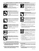
SECTION 1 − SAFETY PRECAUTIONS - READ BEFORE USING som _3/05 Y Warning: Protect yourself and others from injury — read and follow these precautions. 1-1. Symbol Usage Means Warning! Watch Out! There are possible hazards with this procedure! The possible hazards are shown in the adjoining symbols. Y Marks a special safety message. . Means “Note”; not safety related. This group of symbols means Warning! Watch Out! possible ELECTRIC SHOCK, MOVING PARTS, and HOT PARTS hazards.
ARC RAYS can burn eyes and skin. Arc rays from the welding process produce intense visible and invisible (ultraviolet and infrared) rays that can burn eyes and skin. Sparks fly off from the weld. D Wear an approved welding helmet fitted with a proper shade of filter lenses to protect your face and eyes when welding or watching (see ANSI Z49.1 and Z87.1 listed in Safety Standards). D Wear approved safety glasses with side shields under your helmet.
1-3. Additional Symbols For Installation, Operation, And Maintenance FIRE OR EXPLOSION hazard. MOVING PARTS can cause injury. D Do not install or place unit on, over, or near combustible surfaces. D Do not install unit near flammables. D Do not overload building wiring − be sure power supply system is properly sized, rated, and protected to handle this unit. D Keep away from moving parts such as fans. D Keep all doors, panels, covers, and guards closed and securely in place.
1-5. Principal Safety Standards Safety in Welding, Cutting, and Allied Processes, ANSI Standard Z49.1, from Global Engineering Documents (phone: 1-877-413-5184, website: www.global.ihs.com). Boulevard, Rexdale, Ontario, Canada M9W 1R3 (phone: 800−463−6727 or in Toronto 416−747−4044, website: www.csa−international.org). Recommended Safe Practices for the Preparation for Welding and Cutting of Containers and Piping, American Welding Society Standard AWS F4.
SECTION 2 − CONSIGNES DE SÉCURITÉ − LIRE AVANT UTILISATION fre_som _3/05 Y Avertissement : se protéger et protéger les autres contre le risque de blessure — lire et respecter ces consignes. 2-1. Symboles utilisés Symbole graphique d’avertissement ! Attention ! Cette procédure comporte des risques possibles ! Les dangers éventuels sont représentés par les symboles graphiques joints. Y Indique un message de sécurité particulier . Signifie NOTE ; n’est pas relatif à la sécurité. 2-2.
LES RAYONS D’ARC peuvent entraîner des brûlures aux yeux et à la peau. Le rayonnement de l’arc du procédé de soudage génère des rayons visibles et invisibles intenses (ultraviolets et infrarouges) susceptibles de provoquer des brûlures dans les yeux et sur la peau. Des étincelles sont projetées pendant le soudage. D Porter un casque de soudage approuvé muni de verres filtrants approprié pour protéger visage et yeux pendant le soudage (voir ANSI Z49.1 et Z87.1 énuméré dans les normes de sécurité).
2-3. Dangers supplémentaires en relation avec l’installation, le fonctionnement et la maintenance Risque D’INCENDIE OU D’EXPLOSION. DES ORGANES MOBILES peuvent provoquer des blessures. D Ne pas placer l’appareil sur, au-dessus ou à proximité de surfaces inflammables. D Ne pas installer l’appareil à proximité de produits inflammables. D Ne pas surcharger l’installation électrique − s’assurer que l’alimentation est correctement dimensionnée et protégée avant de mettre l’appareil en service.
2-5. Principales normes de sécurité Safety in Welding, Cutting, and Allied Processes, ANSI Standard Z49.1, de Global Engineering Documents (téléphone : 1-877-413-5184, site Internet : www.global.ihs.com). Boulevard, Rexdale, Ontario, Canada M9W 1R3 (téléphone : 800-463-6727 ou à Toronto 416-747-4044, site Internet : www.csa-international.org). Recommended Safe Practices for the Preparation for Welding and Cutting of Containers and Piping, American Welding Society Standard AWS F4.
SECTION 3 − SPECIFICATIONS 3-1. Specifications Rated Welding Output Maximum OpenCircuit Voltage DC Amperage Range 90 A @ 19 Volts DC, 20% Duty Cycle 30 − 125 63 A @ 21 Volts DC, 20% Duty Cycle* Wire Type And Dia Amperes Input at Rated Load Output 115 V, 60 Hz, SinglePhase KVA KW 20 2.90 2.50 15* 2.20* 1.77* 29 Weight W/ Gun 50 lb (22.7 kg) Flux Cored Solid/ Stainless** Wire Feed Speed Range .030 − .035 in (0.8 − 0.9 mm) .024 − .030 in (0.6 − 0.
3-3. Volt-Ampere Curves 33.0 The volt-ampere curves show the minimum and maximum voltage and amperage output capabilities of the welding power source. Curves of other settings fall between the curves shown. Voltage 28.0 23.0 18.0 13.0 8.0 0.0 10.0 20.0 30.0 40.0 50.0 60.0 70.0 80.0 90.0 100.0110.0 120.0130.0 Amperage Range 1 Range 2 Range 3 Range 4 ssb1.1 10/91 − 210 518 SECTION 4 − INSTALLATION 4-1. Installing Work Clamp . Connection hardware must be tightened with proper tools.
4-2. Process/Polarity Table Process Polarity Cable Connections Cable To Gun Cable To Work Clamp FCAW − Self-shielding wire − no shielding gas DCEN − Straight Polarity Connect to negative (−) output terminal Connect to positive (+) output terminal GMAW* − Solid wire with shielding gas DCEP − Reverse polarity Connect to positive (+) output terminal Connect to negative (−) output terminal * Unit must have MIG conversion kit 195 158 installed. 4-3.
4-4. Installing Gas Supply NOTE This Section only applies to MIG units or units equipped with MIG kit. 1 Tools Needed: 4 11/16, 1-1/8 in 2 6 5 3 7 Shielding Gas 802 028 / Ref. 803 379-A Obtain gas cylinder and chain to running gear, wall, or other stationary support so cylinder cannot fall and break off valve. Install regulator/flowmeter to cylinder valve. Be sure that gauge face is vertical for viewing and adjusting.
4-5. Installing Wire Spool And Adjusting Hub Tension Installing 4 in (102 mm) Wire Spool When a slight force is needed to turn spool, tension is set. Installing 8 in (203 mm) Wire Spool Adapter used with 8 in (203 mm) spool only. . Only applies to units equipped with optional hub kit. When a slight force is needed to turn spool, tension is set. Retaining ring used with 8 in (203 mm) spool only. Tools Needed: 1/2 in Ref.
4-6. Selecting A Location And Connecting Input Power For 115 VAC Model 1 2 Rating Label Grounded Receptacle A 115 volt, 20 ampere individual branch circuit protected by time-delay fuses or circuit breaker is required. 3 Plug From Unit Select extension cord of 14 AWG for up to 50 ft (15 m) or 12 AWG for 50 up to 200 ft (61 m). Y Special installation may be required where gasoline or volatile liquids are present − see NEC Article 511 or CEC Section 20. Y Do not move or operate unit where it could tip.
4-7. Installing Contact Tip And Nozzle Y Turn off welding power source. 1 Nozzle Remove nozzle. 2 Contact Tip 3 Tip Adapter Thread welding wire through gun (see Section 4-8). 2 3 Slide contact tip over wire and tighten tip into tip adapter. Install nozzle. 1 Flux Nozzle MIG Nozzle Use with flux cored wire only. Narrow design allows access in tight spaces and provides better visibility of puddle during welding. Use with solid or flux cored wire.
4-8. Threading Welding Wire 1 2 3 4 5 6 Wire Spool Welding Wire Inlet Wire Guide Pressure Adjustment Knob Drive Roll Gun Cable Lay gun cable out straight. 4 Tools Needed: 1 2 3 6 5 . Hold wire tightly to keep it from unraveling. 6 in (150 mm) Open pressure assembly. Tighten Pull and hold wire; cut off end. 4 in (102 mm) Push wire thru guides into gun liner; continue to hold wire. .
SECTION 5 − OPERATION 5-1. Controls 1 Voltage Switch Use control to select the weld voltage range. As the thickness of material increases, a higher voltage range must be selected (see weld setting label in welding power source or Section 5-3 as applicable). Do not switch under load. 2 . Switch must “click” into detent position for weld output. 2 Wire Feed Control Use control to select a wire feed speed.
5-3.
210 428 OM-947 Page 19
SECTION 6 − MAINTENANCE &TROUBLESHOOTING 6-1. Routine Maintenance Y Disconnect power before maintaining. 3 Months Replace unreadable labels. Repair or replace cracked weld cable. Clean and tighten weld terminals. 6 Months Blow out or vacuum inside. During heavy service, clean monthly. Or 6-2. Overload Protection 1 Supplementary Protector CB1 CB1 protects unit from overload. If CB1 opens, unit shuts down. 1 Reset supplementary protector. 803 379-A 6-3.
6-4. Changing Drive Roll Or Wire Inlet Guide 1 2 Pressure Adjustment Knob Pressure Assembly Pivot pressure adjustment knob down, and lift pressure assembly up. 3 4 5 6 2 Pivot Tube Plate Securing Screws Pressure Arm Pivot Tube Inlet Wire Guide Remove screws and pivot tube plate. Lift out pressure arm pivot tube, and slide inlet wire guide out of tube. Slide replacement wire guide into tube, and place tube back into drive assembly.
6-5. Replacing Gun Contact Tip Y Turn off welding power source. 1 Nozzle Remove nozzle. 2 Contact Tip 3 Tip Adapter Cut off welding wire at contact tip. Remove contact tip from tip adapter, and install new contact tip. Reinstall nozzle. 2 3 1 Tools Needed: Ref.
6-6. Cleaning Gun Liner Y Turn off welding power source. 1 Nozzle 2 Contact Tip 3 Adapter Head Tube 1 2 3 8 mm Remove nozzle. Cut off wire at contact tip, and remove contact tip and tip adapter. Open pressure assembly. Retract wire from liner onto spool. . Hold wire tightly to keep it from unraveling. Secure end of wire at spool. Remove screws (3) from cover, and remove cover from wire drive assembly. Tools Needed: Lay gun cable out straight, and blow out liner.
6-7. Replacing Gun Liner Y Turn off welding power source. Tools Needed: Head Tube 1 2 8 mm / 10 mm 3 8 mm Remove nozzle. Cut off wire at contact tip, and remove contact tip and tip adapter. Remove screws (3) from cover, and remove cover from wire drive assembly. Open pressure assembly. Retract wire from liner onto spool. Loosen liner setscrew. . Hold wire tightly to keep it from unraveling. Secure end of wire at spool. Twist top and bottom handle locking rings counterclockwise 1/4 turn.
6-7. Replacing Gun Liner (Continued) 13/16 in (21 mm) When liner exits cable at gun handle, guide liner into head tube. Continue to push liner until it exits end of head tube. 3/8 in (10 mm) Be sure that cable is straight. Tighten liner setscrew. Cut liner so that 3/8 in (10 mm) sticks out of head tube. File down any sharp points on liner after cutting to length. Reassemble gun by placing head tube and cable into one half of handle. Be sure trigger is properly installed into trigger slot.
6-8. Troubleshooting Table Trouble Remedy No weld output; wire does not feed; fan Secure power cord plug in receptacle (see Section 4-6). does not run run. Replace building line fuse or reset circuit breaker if open. Place Power switch in On position (see Section 5-1). Reset welding power source supplementary protector if open. No weld output; wire does not feed; fan Thermostat TP1 open (overheating). Allow fan to run with gun trigger switch off; thermostat closes when unit has cooled (see Section 3-2).
SECTION 7 − ELECTRICAL DIAGRAM 230 950-A Figure 6-1.
SECTION 8 − WIRE WELDING GUIDELINES 8-1. Typical FCAW Process Connections Y Weld current can damage electronic parts in vehicles. Disconnect both battery cables before welding on a vehicle. Place work clamp as close to the weld as possible. Wire Feeder/ Power Source Gun Work Clamp Workpiece Self-Shielding Flux Core Wire fcaw 1/2003 / Ref. 803 444-A 8-2. Typical MIG Process Connections Y Weld current can damage electronic parts in vehicles. Disconnect both battery cables before welding on a vehicle.
8-3. Typical Control Settings NOTE These settings are guidelines only. Material and wire type, joint design, fitup, position, etc. affect settings. Test welds to be sure they comply to specifications. Material thickness determines weld parameters. 1/8 or 0.125 in Convert Material Thickness to Amperage (A) (0.001 in = 1 ampere) 0.125 in = 125 A .035 in Wire Size Wire Size Amperage Range 0.023 in 30 − 90 A 0.030 in 40 − 145 A 0.035 in 50 − 180 A Recommendation Wire Speed (Approx.) 0.
8-4. Holding And Positioning Welding Gun NOTE Welding wire is energized when gun trigger is pressed. Before lowering helmet and pressing trigger, be sure wire is no more than 1/2 in (13 mm) past end of nozzle, and tip of wire is positioned correctly on seam.
8-5. Conditions That Affect Weld Bead Shape NOTE Weld bead shape depends on gun angle, direction of travel, electrode extension (stickout), travel speed, thickness of base metal, wire feed speed (weld current), and voltage. . The Drag or Pull technique is generally recommended when welding with flux-cored tubular wire.
8-6. Gun Movement During Welding NOTE Normally, a single stringer bead is satisfactory for most narrow groove weld joints; however, for wide groove weld joints or bridging across gaps, a weave bead or multiple stringer beads works better. 1 1 2 2 3 Stringer Bead − Steady Movement Along Seam Weave Bead − Side To Side Movement Along Seam Weave Patterns Use weave patterns to cover a wide area in one pass of the electrode. 3 S-0054-A 8-7.
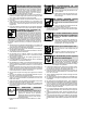
8-9. Troubleshooting − Excessive Spatter Excessive Spatter − scattering of molten metal particles that cool to solid form near weld bead. S-0636 Possible Causes Corrective Actions Wire feed speed too high. Select lower wire feed speed. Voltage too high. Select lower voltage range. Electrode extension (stickout) too long. Use shorter electrode extension (stickout). Workpiece dirty. Remove all grease, oil, moisture, rust, paint, undercoating, and dirt from work surface before welding.
8-12. Troubleshooting − Lack Of Penetration Lack Of Penetration − shallow fusion between weld metal and base metal. Lack of Penetration Good Penetration S-0638 Possible Causes Corrective Actions Improper joint preparation. Material too thick. Joint preparation and design must provide access to bottom of groove while maintaining proper welding wire extension and arc characteristics. Improper weld technique. Maintain normal gun angle of 0 to 15 degrees to achieve maximum penetration.
8-15. Troubleshooting − Waviness Of Bead Waviness Of Bead − weld metal that is not parallel and does not cover joint formed by base metal. S-0641 Possible Causes Corrective Actions Welding wire extends too far out of nozzle. Be sure welding wire extends not more than 1/2 in (13 mm) beyond nozzle. Unsteady hand. Support hand on solid surface or use two hands. 8-16. Troubleshooting − Distortion Distortion − contraction of weld metal during welding that forces base metal to move.
SECTION 9 − PARTS LIST . Hardware is common and 18 25 23 24 6 36 33 4 37 6 34 11 10 9 5 28 31 27 30 26 32 20 43 29 8 1 22 21 12 2 7 38 19 39 40 42 3 13 17 41 35 14 16 15 not available unless listed. 803 446-B Figure 8-1.
Item No. Dia. Mkgs. Part No. Description Quantity Figure 8-1. Main Assembly . . . 1 . . . . . . . . . . . . . . . . . . 210 432 . . . . . . . . . . . . . . . . . . . . . . . . . . . 210 530 . . . . . . 2 . . . . . . . . . . . . . . . . . . 210 433 . . . . . . 3 . . . . . . . . . . . . . . . . . +210 434 . . . . . . 4 . . . . . . . . . . . . . . . . . . 210 435 . . . . . . 5 . . . . . . . . . . . . . . . . . . 213 643 . . . . . . 6 . . . . . . . . . . . . . . . . . . 196 006 . . . . . . 7 . . . . . . .
1 2 5 − See Table 8-1 4 7 7 3 6 804 243-A Figure 8-2. H-9B Gun Item No. Part No. Description 225 397 ... ... ... ... ... ... ... ... ... ... 1 1 2 3 4 5 5 5 6 7 . . . . . . . . . . . . . 169 715 . . . . . . . . . . . . ♦226 190 . . . . . . . . . . . . . 169 716 . . . . . . . . . . . . . 225 410 . . . . . . . . . . . . . 210 970 . . . . . . . . . . . . ♦087 299 . . . . . . . . . . . . . 000 067 . . . . . . . . . . . . ♦000 068 . . . . . . . . . . . . . 226 010 . . . . . . . . . . . . .
1 6 7 8 5 9 2 3 803 442-B 4 Figure 8-3. Wire Drive Assembly Item No. ... ... ... ... ... ... ... ... ... 1 2 3 4 5 6 7 8 9 Part No. .................. .................. .................. .................. .................. .................. .................. .................. .................. Description Quantity 209 532 Figure 8-3. Wire Drive Assembly 212 377 . . . . 212 379 . . . . 212 383 . . . . 212 368 . . . . 212 384 . . . . 212 385 . . . . 212 387 . . . . 212 388 . . . .
Notes
Notes
Notes
Effective January 1, 2006 5/3/1 WARRANTY applies to all Hobart welding equipment, plasma cutters and spot welders with a serial number preface LG or newer. Warranty Questions? Call 1-800-332-3281 7 AM − 6 PM EST Service You always get the fast, reliable response you need. Most replacement parts can be in your hands in 24 hours. Support Need fast answers to the tough welding questions? Contact your distributor or call 1-800-332-3281.
Owner’s Record Please complete and retain with your personal records. Model Name Protect Your Investment! Serial/Style Number Purchase Date (Date which equipment was delivered to original customer.) Distributor Address City Register your product at: HobartWelders.com State Zip Resources Available Always provide Model Name and Serial/Style Number. To locate a Distributor, retail or service location: Call 1-877-Hobart1 or visit our website at www.HobartWelders.