OM-227 978A 2006−12 Processes MIG (GMAW) Welding Flux Cored (FCAW) Welding Description Arc Welding Power Source And Wire Feeder Handler 210 R
From Hobart to You Thank you and congratulations on choosing Hobart. Now you can get the job done and get it done right. We know you don’t have time to do it any other way. This Owner’s Manual is designed to help you get the most out of your Hobart products. Please take time to read the Safety precautions. They will help you protect yourself against potential hazards on the worksite. We’ve made installation and operation quick and easy.
TABLE OF CONTENTS SECTION 1 − SAFETY PRECAUTIONS - READ BEFORE USING . . . . . . . . . . . . . . . . . . . . . . . . . . . . . . . . . . . 1-1. Symbol Usage . . . . . . . . . . . . . . . . . . . . . . . . . . . . . . . . . . . . . . . . . . . . . . . . . . . . . . . . . . . . . . . . . . . . . . . . 1-2. Arc Welding Hazards . . . . . . . . . . . . . . . . . . . . . . . . . . . . . . . . . . . . . . . . . . . . . . . . . . . . . . . . . . . . . . . . . . 1-3.
TABLE OF CONTENTS SECTION 9 − MIG WELDING (GMAW) GUIDELINES . . . . . . . . . . . . . . . . . . . . . . . . . . . . . . . . . . . . . . . . . . . . . . 9-1. Typical MIG Process Connections . . . . . . . . . . . . . . . . . . . . . . . . . . . . . . . . . . . . . . . . . . . . . . . . . . . . . . . 9-2. Typical MIG Process Control Settings . . . . . . . . . . . . . . . . . . . . . . . . . . . . . . . . . . . . . . . . . . . . . . . . . . . . 9-3. Holding And Positioning Welding Gun . . . . . . . . . . . . .
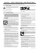
SECTION 1 − SAFETY PRECAUTIONS - READ BEFORE USING som _3/05 Y Warning: Protect yourself and others from injury — read and follow these precautions. 1-1. Symbol Usage Means Warning! Watch Out! There are possible hazards with this procedure! The possible hazards are shown in the adjoining symbols. Y Marks a special safety message. . Means “Note”; not safety related. This group of symbols means Warning! Watch Out! possible ELECTRIC SHOCK, MOVING PARTS, and HOT PARTS hazards.
ARC RAYS can burn eyes and skin. Arc rays from the welding process produce intense visible and invisible (ultraviolet and infrared) rays that can burn eyes and skin. Sparks fly off from the weld. D Wear an approved welding helmet fitted with a proper shade of filter lenses to protect your face and eyes when welding or watching (see ANSI Z49.1 and Z87.1 listed in Safety Standards). D Wear approved safety glasses with side shields under your helmet.
1-3. Additional Symbols For Installation, Operation, And Maintenance FIRE OR EXPLOSION hazard. MOVING PARTS can cause injury. D Do not install or place unit on, over, or near combustible surfaces. D Do not install unit near flammables. D Do not overload building wiring − be sure power supply system is properly sized, rated, and protected to handle this unit. D Keep away from moving parts such as fans. D Keep all doors, panels, covers, and guards closed and securely in place.
1-5. Principal Safety Standards Safety in Welding, Cutting, and Allied Processes, ANSI Standard Z49.1, from Global Engineering Documents (phone: 1-877-413-5184, website: www.global.ihs.com). Boulevard, Rexdale, Ontario, Canada M9W 1R3 (phone: 800−463−6727 or in Toronto 416−747−4044, website: www.csa−international.org). Recommended Safe Practices for the Preparation for Welding and Cutting of Containers and Piping, American Welding Society Standard AWS F4.
SECTION 2 − CONSIGNES DE SÉCURITÉ − LIRE AVANT UTILISATION fre_som _3/05 Y Avertissement : se protéger et protéger les autres contre le risque de blessure — lire et respecter ces consignes. 2-1. Symboles utilisés Symbole graphique d’avertissement ! Attention ! Cette procédure comporte des risques possibles ! Les dangers éventuels sont représentés par les symboles graphiques joints. Y Indique un message de sécurité particulier . Signifie NOTE ; n’est pas relatif à la sécurité. 2-2.
LES RAYONS D’ARC peuvent entraîner des brûlures aux yeux et à la peau. Le rayonnement de l’arc du procédé de soudage génère des rayons visibles et invisibles intenses (ultraviolets et infrarouges) susceptibles de provoquer des brûlures dans les yeux et sur la peau. Des étincelles sont projetées pendant le soudage. D Porter un casque de soudage approuvé muni de verres filtrants approprié pour protéger visage et yeux pendant le soudage (voir ANSI Z49.1 et Z87.1 énuméré dans les normes de sécurité).
2-3. Dangers supplémentaires en relation avec l’installation, le fonctionnement et la maintenance Risque D’INCENDIE OU D’EXPLOSION. DES ORGANES MOBILES peuvent provoquer des blessures. D Ne pas placer l’appareil sur, au-dessus ou à proximité de surfaces inflammables. D Ne pas installer l’appareil à proximité de produits inflammables. D Ne pas surcharger l’installation électrique − s’assurer que l’alimentation est correctement dimensionnée et protégée avant de mettre l’appareil en service.
2-5. Principales normes de sécurité Safety in Welding, Cutting, and Allied Processes, ANSI Standard Z49.1, de Global Engineering Documents (téléphone : 1-877-413-5184, site Internet : www.global.ihs.com). Boulevard, Rexdale, Ontario, Canada M9W 1R3 (téléphone : 800-463-6727 ou à Toronto 416-747-4044, site Internet : www.csa-international.org). Recommended Safe Practices for the Preparation for Welding and Cutting of Containers and Piping, American Welding Society Standard AWS F4.
SECTION 3 − DEFINITIONS 3-1. Symbols And Definitions A V Amperage Hz Voltage Hertz Negative Positive Direct Current (DC) Single Phase Input Output Voltage Input Off On Do Not Switch While Welding Gas Metal Arc Welding (GMAW) Wire Feed Flux Cored Arc Welding (FCAW) SECTION 4 − SPECIFICATIONS 4-1.
4-2. Duty Cycle And Overheating Output Amperes Duty Cycle is percentage of 10 minutes that unit can weld at rated load without overheating. If unit overheats, thermostat(s) opens, output stops, and cooling fan runs. Wait fifteen minutes for unit to cool. Reduce amperage or duty cycle before welding. 200 175 130 100 80 60 Y Exceeding duty cycle can damage unit or gun and void warranty.
SECTION 5 − INSTALLATION 5-1. Installing Welding Gun 1 2 3 4 Loosen thumbscrew. Insert end through opening until it bottoms against drive assembly. Tighten thumbscrew. Spool Gun Welding gun must be inserted completely to prevent leakage of shielding gas. 5 6 Drive Assembly MIG Gun Gun Securing Thumbscrew Gun End ÉÉÉ ÉÉÉ ÉÉÉ 5 Gun Trigger Plug Insert plug into receptacle, and tighten threaded collar. 6 Spool Gun/MIG Gun Switch Place switch in MIG Gun position. Close door. MIG Gun 1 3 2 4 .
5-3. Process/Polarity Table Process Cable Connections Polarity Cable To Gun Cable To Work GMAW − Solid wire with shielding gas DCEP − Reverse polarity Connect to positive (+) output terminal Connect to negative (−) output terminal FCAW − Self-shielding wire − no shielding gas DCEN − Straight Polarity Connect to negative (−) output terminal Connect to positive (+) output terminal 5-4.
5-5. Installing Gas Supply Obtain gas cylinder and chain to running gear, wall, or other stationary support so cylinder cannot fall and break off valve. . DO NOT use Argon/Mixed gas regulator/flowmeter with CO2 shielding gas. See Parts List for optional CO2 gas regulator/flowmeter. 1 1 Cap 2 Cylinder Valve Remove cap, stand to side of valve, and open valve slightly. Gas flow blows dust and dirt from valve. Close valve. 4 2 7 3 3 Cylinder 4 Regulator/Flowmeter Install so face is vertical.
5-6. Selecting A Location And Connecting Input Power Y Special installation may be required where gasoline or volatile liquids are present − see NEC Article 511 or CEC Section 20. Y Installation must meet all National and Local Codes − have only qualified persons make this installation. 18 in (457 mm) of space for airflow Y Disconnect and lockout/tagout input power before connecting input conductors from unit.
5-7. Electrical Service Guide Input Voltage 230 Input Amperes At Rated Output 24 Max Recommended Standard Fuse Or Circuit Breaker Rating In Amperes Circuit Breaker 1, Time-Delay 2 25 Normal Operating 3 35 14 Min Input Conductor Size In AWG 55 (17) Max Recommended Input Conductor Length In Feet (Meters) 14 Min Grounding Conductor Size In AWG Reference: 1999 National Electrical Code (NEC) 1 Choose a circuit breaker with time-current curves comparable to a Time Delay Fuse.
5-9. Installing Contact Tip And Nozzle Y Turn off welding power source. 1 Nozzle Remove nozzle. Contact Tip 3 Tip Adapter Thread welding wire through gun (see Section 5-11). 3 2 Slide contact tip over wire and tighten tip into tip adapter. Install nozzle. 1 Flux Nozzle 2 MIG Nozzle Use with flux cored wire only. Narrow design allows access in tight spaces and provides better visibility of puddle during welding. Use with solid or flux cored wire.
5-10. Connecting Optional Spool Gun 1 2 3 4 7 Loosen thumbscrew. Insert end through opening until it bottoms against drive assembly. Tighten thumbscrew. Spool Gun ÇÇ ÇÇ Drive Assembly Spool Gun Gun Securing Thumbscrew Gun End 5 Spool gun must be inserted completely to prevent leakage of shielding gas. 5 Gun Trigger Plug Insert plug into receptacle, and tighten threaded collar. 6 6 7 2 4 3 1 3 Close door.
5-11. Threading Welding Wire 1 2 3 4 5 6 4 Wire Spool Welding Wire Inlet Wire Guide Pressure Adjustment Knob Drive Roll Gun Conduit Cable Lay gun cable out straight. 6 Tools Needed: 1 2 3 5 . Hold wire tightly to keep it from unraveling. 4 in (120 mm) 6 in (150 mm) Open pressure assembly. Make sure feed roll is set to correct groove to match wire size (see Section 7-4). Pull and hold wire; cut off end. . Use pressure indicator Tighten scale to set a desired drive roll pressure.
SECTION 6 − OPERATION 6-1. Controls 1 2 4 5 3 1 Wire Speed Control Use control to select a wire feed speed. As Voltage switch setting increases, wire speed range also increases (see weld setting label in welding power source or Section 6-2, as applicable). 2 3 Power Switch Voltage Switch The higher the selected number, the thicker the material that can be welded (see weld setting label in welding power source or Section 6-2, as applicable). Do not switch under load. Ref. 227 950-A .
6-2.
227 949-A OM-227 978 Page 21
SECTION 7 − MAINTENANCE &TROUBLESHOOTING 7-1. Routine Maintenance . Maintain more often Y Disconnect power before maintaining. n = Check Z = Change ~ = Clean * To be done by Factory Authorized Service Agent Every 3 Months l Unreadable Labels ~ Weld Terminals nl Cords nl Gun Cables Every 6 Months during severe conditions. l = Replace l Damaged Gas Hose Reference nl Weld Cables OR ~ Drive Rolls ~ Inside Unit 7-2.
7-4. Changing Drive Roll Or Wire Inlet Guide 1 2 Inlet Wire Guide Securing Screw Inlet Wire Guide Loosen screw. Slide tip as close to drive rolls as possible without touching. Tighten screw. 1 3 4 2 Retaining Pin To remove drive roll, push drive roll in and rotate it (1/4 turn) to the open slot and slide it out over the retaining pin. To secure drive roll, locate open slot and push drive roll completely over retaining pin, then rotate drive roll (1/4 turn) to closed slot. Tools Needed: 4 3 .030/.
7-6. Cleaning Or Replacing Gun Liner Tools Needed: Y Disconnect gun from unit. 8 mm / 10mm Head Tube Remove nozzle, contact tip, adapter, and gas diffuser. 8 mm 10 mm Remove liner. To Reassemble Gun: Insert new liner. Install wire outlet guide so that 1/8 in (3 mm) of liner sticks out. Hand tighten outlet guide, and then tighten two full turns more. Lay gun cable out straight before installing new liner. Blow out gun casing. Cut liner off so that 3/4 in (19 mm) sticks out of head tube.
7-7. Replacing Switch And/Or Head Tube Y Turn Off welding power source /wire feeder and disconnect gun. 1 Remove handle locking nut. 3 2 Slide handle. Remove switch housing. Install new switch and connect leads (polarity is not important). Reassemble in reverse order. If replacing head tube, continue to end of figure. 4 Secure head tube in vice. 5 6 Loosen jam nut. Remove from vice and turn head tube out by hand. Hand-tighten head tube into cable connector.
7-8. Troubleshooting Table Trouble Remedy No weld output; wire does not feed; fan Secure power cord plug in receptacle (see Section 5-6). does not run run. Replace building line fuse or reset circuit breaker if open. Place Power switch in On position (see Section 6-1). Reset welding power source supplementary protector (see Section 7-2). No weld output; wire does not feed; fan Thermostat TP1 open (overheating).
Notes OM-227 978 Page 27
SECTION 8 − ELECTRICAL DIAGRAM Figure 8-1.
227 951-A OM-227 978 Page 29
SECTION 9 − MIG WELDING (GMAW) GUIDELINES 9-1. Typical MIG Process Connections Y Weld current can damage electronic parts in vehicles. Disconnect both battery cables before welding on a vehicle. Place work clamp as close to the weld as possible. Regulator/ Flowmeter Wire Feeder/ Power Source Shielding Gas Gas Hose Gun Work Clamp Workpiece light mig 5/97 / Ref.
9-2. Typical MIG Process Control Settings NOTE These settings are guidelines only. Material and wire type, joint design, fitup, position, shielding gas, etc. affect settings. Test welds to be sure they comply to specifications. Material thickness determines weld parameters. 1/8 or 0.125 in Convert Material Thickness to Amperage (A) (0.001 in = 1 ampere) 0.125 in = 125 A .035 in Wire Size Wire Size Amperage Range 0.023 in 30 − 90 A 0.030 in 40 − 145 A 0.
9-3. Holding And Positioning Welding Gun NOTE Welding wire is energized when gun trigger is pressed. Before lowering helmet and pressing trigger, be sure wire is no more than 1/2 in (13 mm) past end of nozzle, and tip of wire is positioned correctly on seam. 1 1 3 2 2 3 4 Hold Gun and Control Gun Trigger Workpiece Work Clamp Electrode Extension (Stickout) 1/4 to 1/2 in (6 To 13 mm) Hold a shorter stickout when welding with solid wire and using a shielding gas.
9-4. Conditions That Affect Weld Bead Shape NOTE Weld bead shape depends on gun angle, direction of travel, electrode extension (stickout), travel speed, thickness of base metal, wire feed speed (weld current), and voltage. 10° Push 10° . Use a Drag Technique with self-shielding flux cored wire.
9-5. Gun Movement During Welding NOTE Normally, a single stringer bead is satisfactory for most narrow groove weld joints; however, for wide groove weld joints or bridging across gaps, a weave bead or multiple stringer beads works better. 1 1 2 2 3 Stringer Bead − Steady Movement Along Seam Weave Bead − Side To Side Movement Along Seam Weave Patterns Use weave patterns to cover a wide area in one pass of the electrode. 3 S-0054-A 9-6.
9-8. Troubleshooting − Excessive Spatter Excessive Spatter − scattering of molten metal particles that cool to solid form near weld bead. S-0636 Possible Causes Corrective Actions Wire feed speed too high. Select lower wire feed speed. Voltage too high. Select lower voltage range. Electrode extension (stickout) too long. Use shorter electrode extension (stickout). Workpiece dirty. Remove all grease, oil, moisture, rust, paint, undercoating, and dirt from work surface before welding.
9-11. Troubleshooting − Lack Of Penetration Lack Of Penetration − shallow fusion between weld metal and base metal. Lack of Penetration Good Penetration S-0638 Possible Causes Corrective Actions Improper joint preparation. Material too thick. Joint preparation and design must provide access to bottom of groove while maintaining proper welding wire extension and arc characteristics. Improper weld technique. Maintain normal gun angle of 0 to 15 degrees to achieve maximum penetration.
9-14. Troubleshooting − Waviness Of Bead Waviness Of Bead − weld metal that is not parallel and does not cover joint formed by base metal. S-0641 Possible Causes Corrective Actions Welding wire extends too far out of nozzle. Be sure welding wire extends not more than 1/2 in (13 mm) beyond nozzle. Unsteady hand. Support hand on solid surface or use two hands. 9-15. Troubleshooting − Distortion Distortion − contraction of weld metal during welding that forces base metal to move.
9-17. Troubleshooting Guide For Semiautomatic Welding Equipment Problem Probable Cause Wire feed motor operates, but Too little pressure on wire feed rolls. wire does not feed feed. Incorrect wire feed rolls. Wire curling up in front of the wire feed rolls (bird nesting) nesting). Wire feeds, but no gas flows. Remedy Increase pressure setting on wire feed rolls. Check size stamped on wire feed rolls, replace to match wire size and type if necessary. Wire spool brake pressure too high.
Notes OM-227 978 Page 39
22 SECTION 10 − PARTS LIST . Hardware is common and 58 24 40 56 55 44 41 42 54 46 45 51 50 47 1 43 48 38 33 39 30 32 2 49 31 36 37 34 35 3 4 29 5 6 7 8 28 9 52 57 10 11 27 12 13 26 25 23 17 16 14 20 15 19 21 18 53 not available unless listed. 804 691-A Figure 10-1.
Item No. Dia. Mkgs. Part No. Description Quantity Figure 10-1. Main Assembly ... ... ... ... ... ... ... ... ... ... ... ... ... ... ... ... ... ... ... ... ... ... ... ... ... ... ... ... ... ... ... ... ... ... ... ... ... ... ... 1 2 3 4 5 6 7 8 9 10 11 12 13 14 15 16 17 18 19 20 21 22 23 24 25 26 27 28 29 30 31 32 33 34 35 36 37 38 39 . . . . . . . . . . . . . . . 199 566 . . . . . . . . . . . . . . . 196 006 . . . . . . . . . . . . . . . 211 887 . . . . . . . . . . . . . . . 204 608 . . . . . .
Item No. Dia. Mkgs. Part No. Description Quantity Figure 10-1. Main Assembly (Continued) ... ... ... ... ... ... ... ... ... ... ... ... ... ... ... ... ... ... ... 40 41 42 43 44 45 46 47 48 49 50 51 52 53 54 55 56 57 58 . . . . . . . . . . . . . . . 196 574 . . SWITCH, rocker DPST . . . . . . . . . . . . . . . . . . . . . . . . . . . . . . . . . . . . . . . . . . . . . . . . . . . . . . . . 228 400 . . KNOB, pointer (voltage) . . . . . . . . . . . . . . . . . . . . . . . . . . . . . . . . . . . . .
1 3 2 4 5 6 7 12 9 8 11 10 804 692-A Figure 10-2. H-14 Gun Item No. Part No. 231 204 ... ... ... ... ... ... ... ... ... ... ... ... ... ... ... ... ... ... ... 1 1 2 2 2 2 3 4 5 6 7 8 9 9 9 9 10 11 12 Description Quantity Figure 10-2. H-14 Gun . . . . . . . . . . . . . . . . . . . . . . . . . . NOZZLE, slip type .500 orf flush (see Section 10-5) . . . . . . . . . . . . . . . . . . . . . . . . . . NOZZLE, flux cored slip type (see Section 10-5) . . . . . . . . . . . . . . . . . . . . . . .
10-3. Optional Drive Rolls For All Feed Head Assemblies WIRE DIAMETER INCHES (mm) PART NO. 202 925 .023/.025 (.6) and .030/.035 (.8 and .9) 202 926 .030/.035 (.8 and .9) and .045 (1.2 VK Groove) 10-4. Options PART NO. DESCRIPTION REMARKS 770 187 Running Gear/Cylinder Rack For One Small Gas Cylinder, 100 lb (45 kg) max. 194 776 Small Running Gear/Cylinder Rack For One Small Gas Cylinder, 75 lb (34 kg) max. 231 204 H-14 Replacement Gun 10 ft length/.030-.
Notes
Notes Work like a Pro! Pros weld and cut safely. Read the safety rules at the beginning of this manual.
Effective January 1, 2006 5/3/1 WARRANTY applies to all Hobart welding equipment, plasma cutters and spot welders with a serial number preface LG or newer. Warranty Questions? Call 1-800-332-3281 7 AM − 6 PM EST Service You always get the fast, reliable response you need. Most replacement parts can be in your hands in 24 hours. Support Need fast answers to the tough welding questions? Contact your distributor or call 1-800-332-3281.
Owner’s Record Please complete and retain with your personal records. Model Name Protect Your Investment! Serial/Style Number Purchase Date (Date which equipment was delivered to original customer.) Distributor Address City Register your product at: HobartWelders.com State Zip Resources Available Always provide Model Name and Serial/Style Number. To locate a Distributor, retail or service location: Call 1-877-Hobart1 or visit our website at www.HobartWelders.