OM-927 199 213L 2006−10 Processes Gas Metal Arc (MIG) Welding Flux Cored Arc (FCAW) Welding Description Arc Welding Power Source and Wire Feeder IronMan 210 And M-10 Gun ™ Includes Installation Instructions For Optional Spoolmate Spoolgun Switch File: MIG (GMAW)
From Hobart to You Thank you and congratulations on choosing Hobart. Now you can get the job done and get it done right. We know you don’t have time to do it any other way. This Owner’s Manual is designed to help you get the most out of your Hobart products. Please take time to read the Safety precautions. They will help you protect yourself against potential hazards on the worksite. We’ve made installation and operation quick and easy.
TABLE OF CONTENTS SECTION 1 − SAFETY PRECAUTIONS - READ BEFORE USING . . . . . . . . . . . . . . . . . . . . . . . . . . . . . . . . . . . 1-1. Symbol Usage . . . . . . . . . . . . . . . . . . . . . . . . . . . . . . . . . . . . . . . . . . . . . . . . . . . . . . . . . . . . . . . . . . . . . . . . 1-2. Arc Welding Hazards . . . . . . . . . . . . . . . . . . . . . . . . . . . . . . . . . . . . . . . . . . . . . . . . . . . . . . . . . . . . . . . . . . 1-3.
TABLE OF CONTENTS SECTION 6 − MIG WELDING (GMAW) GUIDELINES . . . . . . . . . . . . . . . . . . . . . . . . . . . . . . . . . . . . . . . . . . . . . . 6-1. Typical MIG Process Connections . . . . . . . . . . . . . . . . . . . . . . . . . . . . . . . . . . . . . . . . . . . . . . . . . . . . . . . 6-2. Typical MIG Process Control Settings . . . . . . . . . . . . . . . . . . . . . . . . . . . . . . . . . . . . . . . . . . . . . . . . . . . . 6-3. Holding And Positioning Welding Gun . . . . . . . . . . . . .
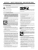
SECTION 1 − SAFETY PRECAUTIONS - READ BEFORE USING som _3/05 Y Warning: Protect yourself and others from injury — read and follow these precautions. 1-1. Symbol Usage Means Warning! Watch Out! There are possible hazards with this procedure! The possible hazards are shown in the adjoining symbols. Y Marks a special safety message. . Means “Note”; not safety related. This group of symbols means Warning! Watch Out! possible ELECTRIC SHOCK, MOVING PARTS, and HOT PARTS hazards.
ARC RAYS can burn eyes and skin. Arc rays from the welding process produce intense visible and invisible (ultraviolet and infrared) rays that can burn eyes and skin. Sparks fly off from the weld. D Wear an approved welding helmet fitted with a proper shade of filter lenses to protect your face and eyes when welding or watching (see ANSI Z49.1 and Z87.1 listed in Safety Standards). D Wear approved safety glasses with side shields under your helmet.
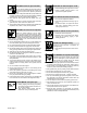
1-3. Additional Symbols For Installation, Operation, And Maintenance FIRE OR EXPLOSION hazard. MOVING PARTS can cause injury. D Do not install or place unit on, over, or near combustible surfaces. D Do not install unit near flammables. D Do not overload building wiring − be sure power supply system is properly sized, rated, and protected to handle this unit. D Keep away from moving parts such as fans. D Keep all doors, panels, covers, and guards closed and securely in place.
1-5. Principal Safety Standards Safety in Welding, Cutting, and Allied Processes, ANSI Standard Z49.1, from Global Engineering Documents (phone: 1-877-413-5184, website: www.global.ihs.com). Boulevard, Rexdale, Ontario, Canada M9W 1R3 (phone: 800−463−6727 or in Toronto 416−747−4044, website: www.csa−international.org). Recommended Safe Practices for the Preparation for Welding and Cutting of Containers and Piping, American Welding Society Standard AWS F4.
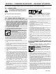
SECTION 2 − CONSIGNES DE SÉCURITÉ − LIRE AVANT UTILISATION fre_som _3/05 Y Avertissement : se protéger et protéger les autres contre le risque de blessure — lire et respecter ces consignes. 2-1. Symboles utilisés Symbole graphique d’avertissement ! Attention ! Cette procédure comporte des risques possibles ! Les dangers éventuels sont représentés par les symboles graphiques joints. Y Indique un message de sécurité particulier . Signifie NOTE ; n’est pas relatif à la sécurité. 2-2.
LES RAYONS D’ARC peuvent entraîner des brûlures aux yeux et à la peau. Le rayonnement de l’arc du procédé de soudage génère des rayons visibles et invisibles intenses (ultraviolets et infrarouges) susceptibles de provoquer des brûlures dans les yeux et sur la peau. Des étincelles sont projetées pendant le soudage. D Porter un casque de soudage approuvé muni de verres filtrants approprié pour protéger visage et yeux pendant le soudage (voir ANSI Z49.1 et Z87.1 énuméré dans les normes de sécurité).
2-3. Dangers supplémentaires en relation avec l’installation, le fonctionnement et la maintenance Risque D’INCENDIE OU D’EXPLOSION. DES ORGANES MOBILES peuvent provoquer des blessures. D Ne pas placer l’appareil sur, au-dessus ou à proximité de surfaces inflammables. D Ne pas installer l’appareil à proximité de produits inflammables. D Ne pas surcharger l’installation électrique − s’assurer que l’alimentation est correctement dimensionnée et protégée avant de mettre l’appareil en service.
2-5. Principales normes de sécurité Safety in Welding, Cutting, and Allied Processes, ANSI Standard Z49.1, de Global Engineering Documents (téléphone : 1-877-413-5184, site Internet : www.global.ihs.com). Boulevard, Rexdale, Ontario, Canada M9W 1R3 (téléphone : 800-463-6727 ou à Toronto 416-747-4044, site Internet : www.csa-international.org). Recommended Safe Practices for the Preparation for Welding and Cutting of Containers and Piping, American Welding Society Standard AWS F4.
SECTION 3 − INTRODUCTION 3-1. Specifications Amps Input at Rated Output, 60 Hz, Single-Phase Rated Output Max. Open Circuit Voltage 200 V 230 V KVA KW 150 A at 23 VDC, 40% Duty Cycle 33 29 2.3* 25 2* 5.8 0.4* 4.9 0.1* No Load Wire Feed Speed Wire Type and Diameter Solid Steel/ Stainless Steel Aluminum Flux Cored .023 − .045 in (0.6 − 1.2 mm) .030 − .035 in (0.8 − 0.9 mm) .030 − .045 in (0.8 − 1.2 mm) 90−750 IPM (2.
3-3. Welding Gun Duty Cycle And Overheating CAUTION WELDING LONGER THAN RATED DUTY CYCLE can damage gun and void warranty. • • Do not weld at rated load longer than shown below. Using gasless flux cored wire reduces gun duty cycle. Definition warn7.1 8/93 .023 To .045 in (0.6 To 1.1 mm) Hard Or Flux Cored Wires 0 .023 To .045 in (0.6 To 1.
3-5. Installing Welding Gun 1 2 3 Drive Assembly Gun Securing Knob Gun End Loosen knob. Insert gun end through opening until it bottoms against drive assembly. Tighten knob. 4 Gun Trigger Plug Insert plug into receptacle, and tighten threaded collar. Close door. 1 3 2 4 Ref.
3-6. Connecting To Weld Output Terminals 1 4 Do not place anything between weld cable terminal and copper bar. 2 Tools Needed: 3 3/4 in (19 mm) 803 778-A Correct Installation Incorrect Installation Y Turn off power before connecting to weld output terminals. 1 Weld Output Terminal 2 Supplied Weld Output Terminal Nut Y Failure to properly connect weld cables may cause excessive heat and start a fire, or damage your machine.
3-8. Setting Gun Polarity For Wire Type 1 2 3 Polarity Changeover Label Positive (+/Red) Output Terminal Negative (−/Black) Output Terminal Always read and follow wire manufacturer’s recommended polarity. Close door. 1 Ref. ST-192 432 2 3 Tools Needed: 3/4 in Ref.
3-9. Installing Gas Supply Obtain gas cylinder and chain to running gear, wall, or other stationary support so cylinder cannot fall and break off valve. . DO NOT use Argon/Mixed gas regulator/flowmeter with CO2 shielding gas. See Parts List for optional CO2 gas regulator/flowmeter. 1 Cap 2 Cylinder Valve Remove cap, stand to side of valve, and open valve slightly. Gas flow blows dust and dirt from valve. Close valve. 3 Cylinder 4 Regulator/Flowmeter Install so face is vertical.
3-10. Installing Wire Spool And Adjusting Hub Tension Use compression spring with 8 in (200 mm) spools. When a slight force is needed to turn spool, tension is set. Installing 1 Or 2 lb Wire Spool Spindle Spindle Install these components onto spindle. To install either a 1 lb or 2 lb wire spool, follow the procedure as shown in the illustration. Order extra spring Part No. 186 437 Remove these components from spindle. Tools Needed: 15/16 in 072573-B / 802 922 3-11.
3-12.
3-13. Selecting A Location And Connecting Input Power Y Do not move or operate unit where it could tip. Y Installation must meet all National and Local Codes − have only qualified persons make this installation. Y Special installation may be required where gasoline or volatile liquids are present − see NEC Article 511 or CEC Section 20. 18 in (457 mm) of space for airflow Y Disconnect and lockout/tagout input power before connecting input conductors from unit.
3-14. Threading Welding Wire 1 2 3 4 5 6 7 4 Wire Spool Welding Wire Inlet Wire Guide Pressure Adjustment Knob Drive Roll Outlet Wire Guide Gun Conduit Cable Lay gun cable out straight. 7 Tools Needed: 1 2 3 5 Ref. 802 601-A 6 . Hold wire tightly to keep it from unraveling. 6 in (150 mm) Open pressure assembly. Pull and hold wire; cut off end. Push wire thru guides into gun; continue to hold wire. . Use pressure indicator Tighten scale to set a desired drive roll pressure.
3-15. Installing Optional Spool Gun Switch In Welding Power Source Y Turn Off unit, and disconnect input power. 1 2 2 3 1 Welding Power Source Center Baffle Switch Location Switch Mounting Plate Remove 2 screws securing switch mounting plate to center baffle. Pull switch mounting plate to pull wiring harness through center baffle hole. 4 Plastic Plug Remove and discard plastic plug from center hole in switch mounting plate panel. 5 Nylon Cable Tie Cut and discard nylon cable tie.
3-16. Connecting Spool Gun To Welding Power Source 5 2 3 5 4 7 1 6 6 Tools Needed: 8 Ref. 802 582-A 3/4 in Y Turn Off unit. negative (−) output terminal. Disconnect and remove MIG (GMAW) welding gun, if applicable. 5 Existing Gas Hose 1 Front Panel Opening 6 Spool Gun Gas Hose 2 Spool Gun Weld Cable 7 Gas Diverter Valve Route weld cable through front panel opening. 3 Positive (+) Output Terminal Connect spool gun weld cable to positive (+) output terminal.
SECTION 4 − OPERATION 4-1. Controls 1 Wire Speed Control The scale around the control is percent, not wire feed speed. 2 Voltage Control The higher the selected number, the thicker the material that can be welded (see welding guide and Section 4-2). 3 Power Switch 1 2 3 Ref.
4-2. Weld Parameters Selecting Wire, Gas and Control Settings What Material are You Welding? Suggested Wire Types Steel Solid (or hard) ER70S−6 Suggested Shielding Gases and Flow Rate Wire Sizes (Diameter) 100% CO2, 20 cfh .023”(0.6 mm) .030”(0.8 mm) .035”(0.9 mm) 75% Ar/25% CO2, 20 cfh (Ar/CO2, produces less spatter − better overall appearance .023”(0.6 mm) .030”(0.8 mm) .035”(0.9 mm) , Steel– for outdoor Fluxcore windy applications or E71T−GS when weld appearance is not critical.
SETTINGS ON THIS CHART ARE STARTING VALUES ONLY AND ARE ON 230 INPUT LINE VOLTAGE. SEE OWNERS MANUAL FOR MORE INFORMATION. To read settings: Number on left of slash Example: 2/4050 = 4 60 40 5 3 is voltage,numberon 70 30 6 2 right of slash is wire 20 80 Select Voltage and Wire Speed Based 1 10 90 on Thickness of Metal Being Welded speed.“—” means not recommended. VOLTA GE WIRE SPEED 3/8” 1/4” 3/16” 1/8” 14 ga. 16 ga. 18 ga. 20 ga. 22 ga.
SECTION 5 − MAINTENANCE AND TROUBLESHOOTING 5-1. Routine Maintenance Y Disconnect power before maintaining. 3 Months Replace unreadable labels. Repair or replace cracked weld cable. Clean and tighten weld terminals. 6 Months Blow out or vacuum inside. During heavy service, clean monthly. OR Remove drive roll and apply light coat of oil or grease to drive motor shaft. 5-2. Supplementary Protectors Y Turn Off unit.
5-3. Replacing Drive Roll And Wire Inlet Guide 1 2 Inlet Wire Guide Securing Screw Inlet Wire Guide Loosen screw. Slide tip as close to drive rolls as possible without touching. Tighten screw. 3 Drive Roll Install correct drive roll for wire size and type. 4 3 Drive Roll Securing Screw Secure drive roll with screw as shown. 2 4 1 Tools Needed: Ref. 802 601-A 5-4. Removing Knob From Front Panel Y Turn Off power.
5-5. Replacing Gun Contact Tip Y Turn Off power before replacing contact tip. 1 2 Nozzle Contact Tip Cut off welding wire at contact tip. Remove nozzle. Remove contact tip and install new contact tip. Reinstall nozzle. 2 1 Tools Needed: Ref.
5-6. Cleaning Or Replacing Gun Liner Tools Needed: Y Disconnect gun from unit. 3/8 in Head Tube Remove nozzle, contact tip, adapter, gas diffuser, and wire outlet guide. 1/2 in Remove liner. Lay gun cable out straight before installing new liner. To Reassemble Gun: Install and tighten new liner. Blow out gun casing. Cut liner off 3/4 in (20 mm) (3/8 in [9.5 mm] for aluminum) from head tube. Install adapter, contact tip, and nozzle. Ref.
5-7. Replacing Switch And/Or Head Tube Y Disconnect gun first. 1 Remove handle locking nut. 3 2 4 Slide handle. Remove switch housing. Note: If installing new switch, push switch lead connectors onto terminal of new switch (polarity is not important). Install switch back into handle, and secure with handle locking nut. If replacing head tube, continue to end of figure. Secure head tube in vice. 5 6 Loosen jam nut. Remove from vice and turn head tube out by hand.
5-8. Welding Troubleshooting Table Welding Trouble No weld output; wire does not feed. Remedy Secure power cord plug in receptacle (see Section 3-13). Check and replace power switch if necessary. Check supplementary protectors CB1 and/or CB2, and reset if necessary (see Section 5-2). Replace building line fuse or reset circuit breaker if open (see Section 3-13). Secure gun trigger plug in receptacle or repair leads, or replace trigger switch (see Sections 3-5 and/or Parts List).
SECTION 6 − MIG WELDING (GMAW) GUIDELINES 6-1. Typical MIG Process Connections Y Weld current can damage electronic parts in vehicles. Disconnect both battery cables before welding on a vehicle. Place work clamp as close to the weld as possible. Regulator/ Flowmeter Shielding Gas Supply Gas Hose Wire Feeder/ Power Source Gun Work Clamp Workpiece light mig 5/967 / Ref.
6-2. Typical MIG Process Control Settings NOTE These settings are guidelines only. Material and wire type, joint design, fitup, position, shielding gas, etc. affect settings. Test welds to be sure they comply to specifications. Material thickness determines weld parameters. 1/8 or 0.125 in Convert Material Thickness to Amperage (A) (0.001 in = 1 ampere) 0.125 in = 125 A .035 in Wire Size Wire Size Amperage Range 0.023 in 30 − 90 A 0.030 in 40 − 145 A 0.
6-3. Holding And Positioning Welding Gun NOTE Welding wire is energized when gun trigger is pressed. Before lowering helmet and pressing trigger, be sure wire is no more than 1/2 in (13 mm) past end of nozzle, and tip of wire is positioned correctly on seam.
6-4. Conditions That Affect Weld Bead Shape NOTE Weld bead shape depends on gun angle, direction of travel, electrode extension (stickout), travel speed, thickness of base metal, wire feed speed (weld current), and voltage.
6-5. Gun Movement During Welding NOTE Normally, a single stringer bead is satisfactory for most narrow groove weld joints; however, for wide groove weld joints or bridging across gaps, a weave bead or multiple stringer beads works better. 1 1 2 2 3 Stringer Bead − Steady Movement Along Seam Weave Bead − Side To Side Movement Along Seam Weave Patterns Use weave patterns to cover a wide area in one pass of the electrode. 3 S-0054-A 6-6.
6-8. Troubleshooting − Excessive Spatter Excessive Spatter − scattering of molten metal particles that cool to solid form near weld bead. S-0636 Possible Causes Corrective Actions Wire feed speed too high. Select lower wire feed speed. Voltage too high. Select lower voltage range. Electrode extension (stickout) too long. Use shorter electrode extension (stickout). Workpiece dirty. Remove all grease, oil, moisture, rust, paint, undercoating, and dirt from work surface before welding.
6-11. Troubleshooting − Lack Of Penetration Lack Of Penetration − shallow fusion between weld metal and base metal. Lack of Penetration Good Penetration S-0638 Possible Causes Corrective Actions Improper joint preparation. Material too thick. Joint preparation and design must provide access to bottom of groove while maintaining proper welding wire extension and arc characteristics. Improper weld technique. Maintain normal gun angle of 0 to 15 degrees to achieve maximum penetration.
6-14. Troubleshooting − Waviness Of Bead Waviness Of Bead − weld metal that is not parallel and does not cover joint formed by base metal. S-0641 Possible Causes Corrective Actions Welding wire extends too far out of nozzle. Be sure welding wire extends not more than 1/2 in (13 mm) beyond nozzle. Unsteady hand. Support hand on solid surface or use two hands. 6-15. Troubleshooting − Distortion Distortion − contraction of weld metal during welding that forces base metal to move.
6-16. Common MIG Shielding Gases This is a general chart for common gases and where they are used. Many different combinations (mixtures) of shielding gases have been developed over the years. The most commonly used shielding gases are listed in the following table.
Problem Probable Cause Remedy Welding arc not stable. Wire slipping in drive rolls. Adjust pressure setting on wire feed rolls. Replace worn drive rolls if necessary. Wrong size gun liner or contact tip. Match liner and contact tip to wire size and type. Incorrect voltage setting for selected wire feed speed on Readjust welding parameters. welding power source. Loose connections at the gun weld cable or work cable. Check and tighten all connections. Gun in poor shape or loose connection inside gun.
Notes OM-927 Page 40
SECTION 7 − ELECTRICAL DIAGRAM 204 205 Figure 7-1.
SECTION 8 − PARTS LIST . Hardware is common and 13 18 21 22 − Fig 8-5 1 20 2 3 19 4 17 − Fig 8-4 5 6 23 7 24 16 9 − Fig 8-2 12 14 15 8 10 − Fig 8-3 11 not available unless listed. 802 602-C Figure 8-1.
Item No. Dia. Mkgs. Part No. Description Quantity Figure 8-1. Main Assembly . . . 1 . . . . . . . . . . 203 481 . . . 2 . . . . . . . . . . 151 187 . . . 3 . . . . . . . . . . 134 464 . . . 4 . . . . . . . . . +205 868 . . . . . . . . . . . . . . . . 199 208 . . . 5 . . . . . . . . . . 205 867 . . . 6 . . . . T1 . . 202 077 . . . 7 . . . . Z . . . 199 220 . . . . . . . . . TP2 . . 213 414 . . . 8 . . . SR1 . . 199 188 . . . . . . . . . TP1 . . 604 515 . . . 9 . . . . . . . . . . . Fig 8-2 . . . 10 . .
10 . Hardware is common and 31 19 23 24 25 22 26 21 20 27 28 1 2 3 4 5 6 29 7 17 8 16 15 9 30 14 13 12 11 not available unless listed. 802 603-B Figure 8-2.
Item No. Dia. Mkgs. Part No. Description Quantity Figure 8-2. Center Baffle w/Components (Fig 8-1 Item 9) . . . 1 . . . . . . . . . . . . . 058 427 . . . 2 . . . . . . . . . . . . . 085 980 . . . 3 . . . . . . . . . . . . . 605 941 . . . 4 . . . . . . . . . . . . . 186 437 . . . 5 . . . . . . . . . . . . . 057 971 . . . 6 . . . . . . . . . . . . . 057 745 . . . 7 . . . . . . . . . . . . . 186 435 . . . 8 . . . . . . . . . . . . . 186 436 . . . 9 . . . . . . . . . . . . . 197 521 . . . . . . . . . . . .
. Hardware is common and not available unless listed. 7 6 8 5 9 10 4 3 2 1 802 283 Figure 8-3. Rear Panel w/Components Item No. Dia. Mkgs. Part No. Description Quantity Figure 8-3. Rear Panel w/Components (Fig 8-1 Item 10) . . . 1 . . . . . . . . . . . . . 049 399 . . . 2 . . . . . . . . . . . . . 148 809 . . . 3 . . . . . M . . . . 188 706 . . . 4 . . . . . . . . . . . . . . 203 711 . . . 5 . . . . . . . . . . . . . 216 396 . . . 6 . . . . . . . . . . . . . 203 478 . . . 7 . . . . . . . . .
. Hardware is common and 2 not available unless listed. 1 3 4 5 11 6 10 9 8 7 802 604-D Figure 8-4. Front Panel w/Components Item No. Dia. Mkgs. Part No. Description Quantity Figure 8-4. Front Panel w/Components (Fig 8-1 Item 17) . . . 1 . . . . . . . . . . . . . 143 974 . . . 2 . . . . . . . . . . . . . 206 589 . . . 3 . . . . . . . . . . . . . 207 074 . . . . . . . . . . . . . . . . . . . 136 343 . . . 4 . . . . . . . . . . . . . 207 077 . . . 5 . . . . . . . . . . . . . 208 207 . . . 6 .
1 3 2 4 5 6 7 14 10 15 8 9 11 13 12 802 388-B Figure 8-5. M-10 Gun Item No. Part No. Description Quantity Figure 8-5. M-10 Gun (Fig 8-1 Item 20 ) ... ... ... ... ... ... ... ... ... ... ... ... ... ... ... ... ... ... ... ... 1 2 2 2 2 3 4 5 6 7 8 9 10 11 12 13 14 14 14 15 . . . . . . . . . . . . . . . 169 715 . . . . . . . . . . . . . ♦087 299 . . . . . . . . . . . . . ♦000 067 . . . . . . . . . . . . . ♦000 068 . . . . . . . . . . . . . ♦000 069 . . . . . . . . . . . . . . . 169 716 . .
Item No. Dia. Mkgs. Part No. Description Quantity Optional Spool Gun Switch ................... ................... ................... ................... ................... 186 420 202 449 605 510 604 804 202 910 .. .. .. .. .. SWITCH ASSY . . . . . . . . . . . . . . . . . . . . . . . . . . . . . . . . . . . . . . . . . . . . . . . . . PLATE, switch . . . . . . . . . . . . . . . . . . . . . . . . . . . . . . . . . . . . . . . . . . . . . . . . . . CABLE TIE . . . . . . . . . . . . . . . . . . . .
Notes
Effective January 1, 2006 5/3/1 WARRANTY applies to all Hobart welding equipment, plasma cutters and spot welders with a serial number preface LG or newer. Warranty Questions? Call 1-800-332-3281 7 AM − 6 PM EST Service You always get the fast, reliable response you need. Most replacement parts can be in your hands in 24 hours. Support Need fast answers to the tough welding questions? Contact your distributor or call 1-800-332-3281.
Owner’s Record Please complete and retain with your personal records. Model Name Protect Your Investment! Serial/Style Number Purchase Date (Date which equipment was delivered to original customer.) Distributor Address City Register your product at: HobartWelders.com State Zip Resources Available Always provide Model Name and Serial/Style Number. To locate a Distributor, retail or service location: Call 1-877-Hobart1 or visit our website at www.HobartWelders.