OM-198 683C April 2000 Processes MIG (GMAW) Welding Flux Cored (FCAW) Welding Description Arc Welding Power Source and Wire Feeder R IronMan 275 With Meters And M-25 Gun Visit our website at www.HobartWelders.
From Hobart to You Thank you and congratulations on choosing Hobart. Now you can get the job done and get it done right. We know you don’t have time to do it any other way. This Owner’s Manual is designed to help you get the most out of your Hobart products. Please take time to read the Safety precautions. They will help you protect yourself against potential hazards on the worksite. We’ve made installation and operation quick and easy.
TABLE OF CONTENTS WARNING This product, when used for welding or cutting, produces fumes or gases which contain chemicals known to the State of California to cause birth defects and, in some cases, cancer. (California Health & Safety Code Section 25249.5 et seq.) The following terms are used interchangeably throughout this manual: MIG = GMAW OM-198 683C SECTION 1 – SAFETY PRECAUTIONS - READ BEFORE USING . . . . . . . . . . . . . . . . . . . . . . . . . . . . 1-1. Symbol Usage . . . . . . . . . . . . . .
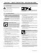
SECTION 1 – SAFETY PRECAUTIONS - READ BEFORE USING som _nd_4/98 1-1. Symbol Usage Means Warning! Watch Out! There are possible hazards with this procedure! The possible hazards are shown in the adjoining symbols. Y Marks a special safety message. . Means “Note”; not safety related. This group of symbols means Warning! Watch Out! possible ELECTRIC SHOCK, MOVING PARTS, and HOT PARTS hazards. Consult symbols and related instructions below for necessary actions to avoid the hazards. 1-2.
ARC RAYS can burn eyes and skin. Arc rays from the welding process produce intense visible and invisible (ultraviolet and infrared) rays that can burn eyes and skin. Sparks fly off from the weld. D Wear a welding helmet fitted with a proper shade of filter to protect your face and eyes when welding or watching (see ANSI Z49.1 and Z87.1 listed in Safety Standards). D Wear approved safety glasses with side shields under your helmet.
1-3. Additional Symbols For Installation, Operation, And Maintenance FIRE OR EXPLOSION hazard. MOVING PARTS can cause injury. D Do not install or place unit on, over, or near combustible surfaces. D Do not install unit near flammables. D Do not overload building wiring – be sure power supply system is properly sized, rated, and protected to handle this unit. D Keep away from moving parts such as fans. D Keep all doors, panels, covers, and guards closed and securely in place.
1-5. EMF Information Considerations About Welding And The Effects Of Low Frequency Electric And Magnetic Fields Welding current, as it flows through welding cables, will cause electromagnetic fields. There has been and still is some concern about such fields.
SECTION 1 – CONSIGNES DE SECURITE – LIRE AVANT UTILISATION som _nd_fre 4/98 1-1. Signification des symboles Signifie Mise en garde ! Soyez vigilant ! Cette procédure présente des risques de danger ! Ceux-ci sont identifiés par des symboles adjacents aux directives. Y Identifie un message de sécurité particulier. . Signifie NOTA ; n’est pas relatif à la sécurité.
LES RAYONS DE L’ARC peuvent provoquer des brûlures dans les yeux et sur la peau. Le rayonnement de l’arc du procédé de soudage génère des rayons visibles et invisibles intenses (ultraviolets et infrarouges) susceptibles de provoquer des brûlures dans les yeux et sur la peau. Des étincelles sont projetées pendant le soudage. D Porter un casque de soudage muni d’un écran de filtre approprié pour protéger votre visage et vos yeux pendant le soudage ou pour regarder (voir ANSI Z49.1 et Z87.
1-3. Dangers supplémentaires en relation avec l’installation, le fonctionnement et la maintenance Risque D’INCENDIE OU D’EXPLOSION. DES ORGANES MOBILES peuvent provoquer des blessures. D Ne pas placer l’appareil sur, au-dessus ou à proximité de surfaces infllammables. D Rester à l’écart des organes mobiles comme le ventilateur. D Maintenir fermés et fixement en place les portes, panneaux, recouvrements et dispositifs de protection.
1-4. Principales normes de sécurité Safety in Welding and Cutting, norme ANSI Z49.1, de l’American Welding Society, 550 N.W. Lejeune Rd, Miami FL 33126 Safety and Health Sandards, OSHA 29 CFR 1910, du Superintendent of Documents, U.S. Government Printing Office, Washington, D.C. 20402. Recommended Safe Practice for the Preparation for Welding and Cutting of Containers That Have Held Hazardous Substances, norme AWS F4.1, de l’American Welding Society, 550 N.W.
SECTION 2 – INSTALLATION 2-1. Specifications Max. OpenCircuit Voltage Rated Output 250 A at 28 VDC, 40% Duty Cycle 200 A at 28 VDC, 60% Duty Cycle Amps Input at Rated Output, 50 or 60 Hz, Single-Phase 200 (208) V 230 V 400 V 460 V 575 V KVA KW 48 2.3* 42 2* 24 1.2* 21 1* 17 0.8* 9.8 0.46* 7.5 0.13* 38 Wire Type and Diameter Solid Steel Stainless Steel Flux Cored .023 – .045 in (0.6 – 1.2 mm) .023 – .035 in (0.6 – 0.9 mm) .030 – .045 in (0.8 – 1.
2-3. Welding Gun Duty Cycle And Overheating CAUTION WELDING LONGER THAN RATED DUTY CYCLE can damage gun and void warranty. • • Do not weld at rated load longer than shown below. Using gasless flux cored wire reduces gun duty cycle. Definition warn7.1 8/93 .023 To .045 in (0.6 To 1.1 mm) Hard Or Flux Cored Wires 0 10 Minutes .023 To .045 in (0.6 To 1.
2-5. Installing Work Clamp 1 2 Work Cable Boot Slide boot onto work cable. Route cable out front panel opening from inside. 3 4 4 5 5 Negative (–) Output Terminal Connect cable to terminal and cover connection with boot. Hardware Work Clamp Route cable through clamp handle and secure as shown. Close door. 1 2 3 Tools Needed: 1/2, 3/4 in 802 474-A 2-6. Installing Welding Gun 1 2 3 Drive Assembly Gun Securing Knob Gun End Loosen securing knob.
2-8. Setting Gun Polarity For Wire Type 1 Changing Polarity Polarity Changeover Label Information Always read and follow manufacture’s recommended polarity. Wire Drive Assembly Lead Work Clamp Lead 1 D D + Positive Terminal - Negative Terminal Shown as shipped – Electrode Positive (DCEP): For solid steel, stainless steel, aluminum, or flux core with gas wires (GMAW). Electrode Negative (DCEN): Reverse lead connections at terminals from that shown above for gasless flux core wires (FCAW).
2-10. Installing Wire Spool and Adjusting Hub Tension Use compression spring with 8 in (200 mm) spools. When a slight force is needed to turn spool, tension is set. Tools Needed: 15/16 in ST-072573-B 2-11. Positioning Jumper Links 230 VOLTS Check input voltage available at site. 1 Jumper Links Access Door Open door. 3 200 VOLTS 460 VOLTS 2 Jumper Link Label Check label – only one is on unit. 3 230 VOLTS 575 VOLTS Input Voltage Jumper Links Move jumper links to match input voltage.
2-12.
2-14. Threading Welding Wire 1 2 3 4 5 6 7 4 7 Wire Spool Welding Wire Inlet Wire Guide Pressure Adjustment Knob Drive Roll Outlet Wire Guide Gun Conduit Cable Lay gun cable out straight. Tools Needed: 1 2 3 5 6 . Hold wire tightly to keep it from unraveling. 6 in (150 mm) Open pressure assembly. Pull and hold wire; cut off end. . Use pressure indicator Tighten scale to set a desired drive roll pressure. 1 2 3 4 Close and tighten pressure assembly, and let go of wire.
2-15.
V V VOL TAGE WIRE SPEED 196 843 OM-198 683 Page 17
SECTION 3 – OPERATION 3-1. Controls 1 Voltage Control Turn control clockwise to increase voltage. 4 2 Wire Speed Control Turn control clockwise to increase wire feed speed.
3-2. Voltmeter And Wire Feed Speed Meter Operation 1 2 Voltmeter Wire Feed Speed Meter Power Up Status 1 Both meters display zeros at unit power up. After one second, preset values appear on both meters. The MIG gun settings (not spool gun) are always the default at initial power up of the unit. Welding Status 2 When either a MIG gun or spool gun trigger is pressed and a welding arc is established, the voltmeter displays actual weld voltage.
SECTION 4 – MAINTENANCE &TROUBLESHOOTING 4-1. Routine Maintenance . Maintain more often Y Disconnect power before maintaining. during severe conditions. 3 Months Replace unreadable labels Repair or replace cracked weld cable Clean and tighten weld terminals 6 Months Blow out or vacuum inside. OR Remove drive roll and carrier. Apply light coat of oil or grease to drive motor shaft. 4-2. Circuit Breaker CB1 1 Circuit Breaker CB1 If CB1 opens, wire feeding stops.
4-4. Replacing Gun Contact Tip Y Turn Off power. 1 2 Nozzle Contact Tip Cut off welding wire at contact tip. Remove nozzle. Remove contact tip and install new contact tip. Reinstall nozzle. 2 1 Tools Needed: Ref. 800 797-C 4-5. Changing Drive Roll and Wire Inlet Guide 1 2 5 3 Loosen screw. Slide tip as close to drive rolls as possible without touching. Tighten screw. 3 2 Securing Screw Inlet Wire Guide Anti-Wear Guide Install guide as shown.
4-6. Aligning Drive Rolls and Wire Guide Y Turn Off power. View is from top of drive rolls looking down with pressure assembly open. Correct 3 Incorrect 4 2 1 5 1 2 3 4 5 Drive Roll Securing Nut Drive Roll Wire Guide Welding Wire Drive Gear Insert screwdriver, and turn screw in or out until drive roll groove lines up with wire guide. Close pressure roll assembly. Tools Needed: Ref.
4-7. Cleaning Or Replacing Gun Liner Tools Needed: Y Disconnect gun from unit first. 5/16 in, 10 mm Head Tube Remove nozzle, contact tip, and adapter. 5/16 in 10 mm Remove liner. Lay gun cable out straight before installing new liner. To Reassemble Gun: Blow out gun casing. Install and tighten new liner. Cut liner off 3/4 in (20 mm) (3/8 in [9.5 mm] for aluminum) from head tube. Install adapter, contact tip, and nozzle. Ref.
4-8. Replacing Switch And/Or Head Tube Y Disconnect gun first. 1 Remove handle locking nut. 3 2 4 Slide handle. Remove switch housing. Note: If installing new switch, push switch lead connectors onto terminal of new switch (polarity is not important). Install switch back into handle, and secure with handle locking nut. If replacing head tube, continue to end of figure. Secure head tube in vice. 5 6 Loosen jam nut. Remove from vice and turn head tube out by hand.
4-9. Troubleshooting Trouble Remedy No weld output; wire does not feed. Be sure line disconnect switch is On (see Section 2-13). Replace building line fuse or reset circuit breaker if open (see Section 2-13). Reset circuit breaker CB1 (see Section 4-2). Secure gun trigger connections (see Section 2-6). Have Factory Authorized Service Agent check Power switch. Have Factory Authorized Service Agent check all board connections and main control board.
Notes OM-198 683 Page 26
SECTION 5 – ELECTRICAL DIAGRAM 197 699-D Figure 5-1.
SECTION 6 – PARTS LIST . Hardware is common and not available unless listed. 802 059-B Figure 6-1.
Item No. Dia. Mkgs. Part No. Description Quantity Figure 6-1. Main Assembly . . . 1 . . . . . . . . . . . . Fig 6-2 . . . 2 . . . . Z1 . . . 199 159 . . . 3 . . . . . . . . . . . . Fig 6-6 . . . 4 . . . . . . . . . . . 146 165 . . . 5 . . . . . . . . . . . 089 899 . . . 6 . . . . . . . . . . . 146 167 . . . . . . . . . . . . . . . . . 198 079 . . . 7 . . . . . . . . . . . 134 464 . . . 8 . . . . . . . . . +170 513 . . . 9 . . . . . . . . . . . 188 911 . . . 9 . . . . . . . . . . . 187 255 . . . 10 . .
. Hardware is common and not available unless listed. 802 060-C Figure 6-2.
Item No. Dia. Mkgs. Part No. Description Quantity Figure 6-2. Baffle, Center w/Components (Fig 6-1 Item 1) . . . 1 . . . . . . . . . . . 058 427 . . . 2 . . . . . . . . . . . 085 980 . . . 3 . . . . . . . . . . . 605 941 . . . 4 . . . . . . . . . . . 186 437 . . . 5 . . . . . . . . . . . 057 971 . . . 6 . . . . . . . . . . . 057 745 . . . 7 . . . . . . . . . . . 186 435 . . . 8 . . . . . . . . . . . 186 436 . . . 9 . . . . . . . . . . . 177 307 . . . 10 . . . . . . . . . . . 196 797 . . . 11 . . . . .
16 12 11 9 14 13 15 12 11 10 9 8 17 7 6 5 4 3 2 1 Ref. 800 792-B Figure 6-3.
Item No. Part No. Description Quantity Figure 6-3. M-25 Gun (Fig 6-1 Item 16 ) ... ... ... ... ... ... ... ... ... ... ... ... ... ... ... ... ... ... ... ... ... ... ... ... ... ... 1 1 1 1 1 2 2 2 2 3 4 5 6 7 8 9 10 11 12 13 14 15 15 15 16 17 . . . . . 200 258 . . . ♦169 724 . . . ♦169 725 . . . ♦169 726 . . . ♦169 727 . . . ♦087 299 . . . ♦000 067 . . . ♦000 068 . . . ♦000 069 . . . . . 169 728 . . . . . 169 729 . . . . . 170 467 . . . . . 170 468 . . . . . 169 730 . . . . . 169 731 . . . . .
Item No. Dia. Mkgs. Part No. Description Quantity Figure 6-4. Panel, Front w/Components (Fig 6-1 Item 15) . . . 1 . . . . . . . . . . . . +196 798 . . . . . . . . . . . . . . . . . . . 198 653 . . . 2 . . . . . . . . . . . . . 196 399 . . . . . . . . PLG10 . . . 130 203 . . . . . . . . . PLG11 . . . 131 203 . . . . . . . . PLG12 . . . 131 204 . . . 3 . . . . . . . . . . . . . 134 201 . . . 4 . . . . . . . . . . . . . 196 801 . . . 5 . C9,10,18, . . . . . . . . . 19,20 . . . 136 735 . . . 6 . . . R2,3 .
Item No. Dia. Mkgs. Part No. Description Quantity Figure 6-5. Wire Drive And Gears (Fig 6-2 Item 26) . . . 1 . . . . . . . . . . . 602 009 . . . 2 . . . . . . . . . . . 172 075 . . . 3 . . . . . . . . . . . 166 072 . . . 4 . . . . . . . . . . . 010 224 . . . 5 . . . . . . . . . . . 182 788 . . . 6 . . . . . . . . . . . 085 242 . . . 7 . . . . . . . . . . . 196 896 . . . 8 . . . . . . . . . . . 196 897 . . . 9 . . . . . . . . . . . 196 895 . . . 10 . . . . . . . . . . . 166 071 . . . 11 . . . . . . . .
Table 6-1. Drive Roll And Wire Guide Kits Note Base selection of drive rolls upon the following recommended usages: 1 2 3 4 5 V-Grooved rolls for hard wire. U-Grooved rolls for soft and soft shelled cored wires. U-Cogged rolls for extremely soft shelled wires (usually hard surfacing types). V-Knurled rolls for hard shelled cored wires. Drive roll types may be mixed to suit particular requirements (example: V-Knurled roll in combination with U-Grooved). Wire Diameter Drive Roll Part No.
Notes
Notes
Effective October 1, 1999 Warranty Questions? Call 1-877-HOBART1 for your local Hobart distributor. Service You always get the fast, reliable response you need. Most replacement parts can be in your hands in 24 hours. Support Need fast answers to the tough welding questions? Contact your distributor or call 1-800-332-3281. The expertise of the distributor and Hobart is there to help you, every step of the way.
Owner’s Record Please complete and retain with your personal records. Model Name Serial/Style Number Purchase Date (Date which equipment was delivered to original customer.) Distributor Address City State Zip Resources Available Always provide Model Name and Serial/Style Number. To locate a Distributor, retail or service location: Contact your Distributor for: Welding Supplies and Consumables Call 1-877-Hobart1 or visit our website at www.HobartWelders.