OM-230 261C 2010−04 Processes MIG (GMAW) Welding Description Wire Feeder Spool Gun Spool Gun DP 3035-10 And DP 3035-20 File: Wire Feeder
From Hobart to You Thank you and congratulations on choosing Hobart. Now you can get the job done and get it done right. We know you don’t have time to do it any other way. This Owner’s Manual is designed to help you get the most out of your Hobart products. Please take time to read the Safety precautions. They will help you protect yourself against potential hazards on the worksite. We’ve made installation and operation quick and easy.
TABLE OF CONTENTS SECTION 1 − SAFETY PRECAUTIONS - READ BEFORE USING . . . . . . . . . . . . . . . . . . . . . . . . . . . . . . . . . 1-1. Symbol Usage . . . . . . . . . . . . . . . . . . . . . . . . . . . . . . . . . . . . . . . . . . . . . . . . . . . . . . . . . . . . . . . . . . . . . . . 1-2. Arc Welding Hazards . . . . . . . . . . . . . . . . . . . . . . . . . . . . . . . . . . . . . . . . . . . . . . . . . . . . . . . . . . . . . . . . . 1-3.
SECTION 1 − SAFETY PRECAUTIONS - READ BEFORE USING som _2010−03 7 Protect yourself and others from injury — read and follow these precautions. 1-1. Symbol Usage DANGER! − Indicates a hazardous situation which, if not avoided, will result in death or serious injury. The possible hazards are shown in the adjoining symbols or explained in the text. Indicates a hazardous situation which, if not avoided, could result in death or serious injury.
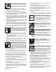
FUMES AND GASES can be hazardous. Welding produces fumes and gases. Breathing these fumes and gases can be hazardous to your health. D Keep your head out of the fumes. Do not breathe the fumes. D If inside, ventilate the area and/or use local forced ventilation at the arc to remove welding fumes and gases. D If ventilation is poor, wear an approved air-supplied respirator.
1-3. Additional Symbols For Installation, Operation, And Maintenance FIRE OR EXPLOSION hazard. D Do not install or place unit on, over, or near combustible surfaces. D Do not install unit near flammables. D Do not overload building wiring − be sure power supply system is properly sized, rated, and protected to handle this unit. FALLING EQUIPMENT can injure. D Use lifting eye to lift unit only, NOT running gear, gas cylinders, or any other accessories.
1-4. California Proposition 65 Warnings Welding or cutting equipment produces fumes or gases which contain chemicals known to the State of California to cause birth defects and, in some cases, cancer. (California Health & Safety Code Section 25249.5 et seq.) Battery posts, terminals and related accessories contain lead and lead compounds, chemicals known to the State of California to cause cancer and birth defects or other reproductive harm. Wash hands after handling.
SECTION 2 − CONSIGNES DE SÉCURITÉ − LIRE AVANT UTILISATION fre_som_2010−03 7 Se protéger et protéger les autres contre le risque de blessure — lire et respecter ces consignes. 2-1. Symboles utilisés DANGER! − Indique une situation dangereuse qui si on l’évite pas peut donner la mort ou des blessures graves. Les dangers possibles sont montrés par les symboles joints ou sont expliqués dans le texte. Indique une situation dangereuse qui si on l’évite pas peut donner la mort ou des blessures graves.
Il reste une TENSION DC NON NÉGLIGEABLE dans les sources de soudage onduleur UNE FOIS l’alimentation coupée. D Arrêter les convertisseurs, débrancher le courant électrique et décharger les condensateurs d’alimentation selon les instructions indiquées dans la partie Entretien avant de toucher les pièces. LES PIÈCES CHAUDES peuvent provoquer des brûlures. D Ne pas toucher à mains nues les parties chaudes. D Prévoir une période de refroidissement avant de travailler à l’équipement.
LES ACCUMULATIONS DE GAZ risquent de provoquer des blessures ou même la mort. D Fermer l’alimentation du gaz protecteur en cas de non-utilisation. D Veiller toujours à bien aérer les espaces confinés ou se servir d’un respirateur d’adduction d’air homologué. Les CHAMPS ÉLECTROMAGNÉTIQUES (CEM) peuvent affecter les implants médicaux. D Les porteurs de stimulateurs cardiaques et autres implants médicaux doivent rester à distance.
Les PIÈCES MOBILES peuvent causer des blessures. LE RAYONNEMENT HAUTE FRÉQUENCE (H.F.) risque de provoquer des interférences. D Ne pas s’approcher des organes mobiles. D Ne pas s’approcher des points de coincement tels que des rouleaux de commande. LES FILS DE SOUDAGE peuvent provoquer des blessures. D Ne pas appuyer sur la gâchette avant d’en avoir reçu l’instruction. D Ne pas diriger le pistolet vers soi, d’autres personnes ou toute pièce mécanique en engageant le fil de soudage.
2-5. Principales normes de sécurité Safety in Welding, Cutting, and Allied Processes, ANSI Standard Z49.1, de Global Engineering Documents (téléphone : 1-877-413-5184, site Internet : www.global.ihs.com). Safe Practices for the Preparation of Containers and Piping for Welding and Cutting, American Welding Society Standard AWS F4.1, de Global Engineering Documents (téléphone : 1-877-413-5184, site internet : www.global.ihs.com).
OM-230 261 Page 10
SECTION 3 − INSTALLATION 3-1. Specifications Approximate Wire Feed Range Wire Diameter Range .030 Thru .035 in. (0.8 Thru 0.9 mm) Aluminum Wire Or Flux Cored Wire .023 Thru 035 in. (0.6 Thru 0.9 mm) Solid Wire 115 To 715 ipm (4.1 To 20.4 mpm) Cooling Method Air Cooled Maximum Spool Size Weld Circuit Rating Overall Dimensions 4 in. (102 mm) Diameter 100 Volts, 150 Amperes, 60% Duty Cycle Using Argon Shielding Gas Length: 11-1/2 in. (291 mm) Width: 2-1/4 in. (57 mm) Height: 8 in.
3-3. Connecting Spool Gun To Handler 210 1 2 3 4 7 Loosen thumbscrew. Insert end through opening until it bottoms against drive assembly. Tighten thumbscrew. Spool Gun ÇÇ ÇÇ Drive Assembly Spool Gun Gun Securing Thumbscrew Gun End 5 Spool gun must be inserted completely to prevent leakage of shielding gas. 5 Gun Trigger Plug Insert plug into receptacle, and tighten threaded collar. 6 6 7 1 3 2 4 3 Exposed O-rings will cause shielding gas leakage.
3-4. Installing Wire Spool And Threading Welding Wire Tools Needed: 6 7 1 Thumb Screw 2 Spool Cover Remove thumb screw and spool cover. 8 3 4 5 Install spool so wire feeds from top. Turn hub tension nut just so a slight drag is felt on the wire spool. 4 2 1 3 9 10 Hub Tension Nut Wire Spool 5 Push Roll/Lower Drive Roll 6 Drive Roll Pressure Adjustment Opening 7 Drive Roll Release Lever (Red) 8 Wire Inlet Guide 9 Contact Tip 10 Nozzle Remove nozzle and contact tip.
SECTION 4 − OPERATION 4-1. Controls . Spool Gun/MIG Gun switch on Handler 210 must be in Spool Gun position for spool gun to operate. 2 1 1 Shielding Gas Cylinder For shielding gas connections, see welding power source Owner’s Manual. 2 Valve Open valve on cylinder just before welding. Close valve on cylinder when finished welding. 3 Spool Gun/MIG Gun Switch Switch must be set in Spool Gun position for spool gun to operate.
SECTION 5 − MAINTENANCE & TROUBLESHOOTING 5-1. Routine Maintenance ! n = Check Z = Change ~ = Clean * To be done by Factory Authorized Service Agent Every 3 Months l Unreadable Labels ~ Weld Terminals nl Cords nl Gun Cables Every 6 Months Disconnect power before maintaining. . Maintain more often during severe conditions.
5-2. Changing Drive Rolls ! Turn off and disconnect input power. 1 Drive Roll Cover Remove cover. Changing Push Roll: To remove push roll: 2 Push Roll Screw 3 Washer 4 Push Roll Remove screw and washer, and lift out drive roll. To install drive roll: 4 Slide drive roll onto shaft and secure with washer and screw. 3 2 It may be necessary to remove drive roll side of gun case to change lower drive roll.
5-3. Changing Liner ! Turn off and disconnect input power. 1 2 3 Nozzle Contact Tip Liner Remove and replace liner. Reinstall parts as shown. 3 2 1 Tools Needed: Ref. 804 687-A 5-4. Troubleshooting Trouble Gun tube assembly loose. Remedy Tighten nut at base of gun tube assembly. No weld output; gun/feeder does not Place Power switch on welding power source in the On position (see welding power source Owner’s work. Manual). Check Spool Gun/MIG Gun switch for correct position. Erratic weld output.
5-5. GMAW (MIG) Aluminum Welding Hints Here are several hints to help you be more successful with your new aluminum feed system. MIG welding aluminum requires different techniques than MIG welding mild steel. A. Before You Start Welding S Material thickness that can be welded with MIG process or aluminum are 14 ga. [0.074 in. (1.9 mm)] or heavier. (How heavy depends on the output capacity of the welder being used.) To MIG weld aluminum thinner than 14 ga.
S Maintain a 3/4 in. (19 mm) tip-to-work distance, and have the contact tip recessed approximately 1/8 in. inside the nozzle if possible. See Figure 5-2. Gas Nozzle Contact Tube Recessed 1/8 in. (3.2 mm) Inside The Nozzle ÇÇÇÇ ÇÇÇÇ ÇÇÇÇ ÇÇÇÇ ÇÇÇÇ ÇÇÇÇ ÉÉÉ ÉÉÉ Contact Tip To Work Distance 3/4 in. (19 mm) Figure 5-2. Contact Tube Position And Tip-To-Work Distance S Avoid large weave beads on aluminum.
SECTION 6 − ELECTRICAL DIAGRAMS 186 451 Figure 6-1.
Notes OM-230 261 Page 21
SECTION 7 − PARTS LIST . Hardware is common and not 20 13 12 14 28 41 40 39 38 37 35 34 36 33 1 2 32 31 44 30 29 27 15 26 16 4 22 5 21 6 17 18 7 19 23 8 2 3 24 25 42 11 9 43 4 10 available unless listed. 804 699-A Figure 7-1.
Item No. Dia. Mkgs. Part No. Description Quantity Figure 7-1. Complete Assembly ... ... ... ... ... ... ... ... ... ... ... ... ... ... ... ... ... ... ... ... ... ... ... ... ... ... ... ... ... ... ... ... ... ... ... ... ... ... ... ... ... ... ... ... ... ... ... ... ... ... ... ... 1 2 3 4 5 6 7 8 9 10 11 12 13 14 15 16 17 18 19 20 21 18 21 22 23 24 25 26 27 27 28 28 29 30 31 32 32 33 34 35 36 37 38 39 39 39 40 41 42 43 44 44 . . . PB1 . . . . . 186 416 . . TRIGGER SWITCH . . . . . . . . . . . .
Notes
Notes
Notes
Effective January 1, 2010 5/3/1 WARRANTY applies to all Hobart welding equipment, plasma cutters and spot welders with a serial number preface of MA or newer. Warranty Questions? Call 1-800-332-3281 7 AM − 5 PM EST Service You always get the fast, reliable response you need. Most replacement parts can be in your hands in 24 hours. Support Need fast answers to the tough welding questions? Contact your distributor or call 1-800-332-3281.
Owner’s Record Please complete and retain with your personal records. Model Name Protect Your Investment! Serial/Style Number Purchase Date (Date which equipment was delivered to original customer.) Distributor Address City Register your product at: HobartWelders.com State Zip Resources Available Always provide Model Name and Serial/Style Number. To locate a Distributor, retail or service location: Call 1-877-Hobart1 or visit our website at www.HobartWelders.