TM-944C October 2003 Handler 135 (500 414) Eff. w/Serial No. LB096205 Handler 175 (500 416) Eff. w/Serial No. LB075197 Processes MIG (GMAW) Welding Flux Cored (FCAW) Welding Description Arc Welding Power Source And Wire Feeder Handler 135 / 175 And H-10 Gun Visit our website at www.HobartWelders.
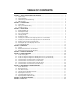
TABLE OF CONTENTS SECTION 1 − SAFETY PRECAUTIONS FOR SERVICING . . . . . . . . . . . . . . . . . . . . . . . . . . . . . . . . . . . . . . . . . . 1-1. Symbol Usage . . . . . . . . . . . . . . . . . . . . . . . . . . . . . . . . . . . . . . . . . . . . . . . . . . . . . . . . . . . . . . . . . . . . . . . . 1-2. Servicing Hazards . . . . . . . . . . . . . . . . . . . . . . . . . . . . . . . . . . . . . . . . . . . . . . . . . . . . . . . . . . . . . . . . . . . . 1-3. California Proposition 65 Warnings . .
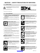
SECTION 1 − SAFETY PRECAUTIONS FOR SERVICING 1-1. Symbol Usage safety_stm 5/97 Means Warning! Watch Out! There are possible hazards with this procedure! The possible hazards are shown in the adjoining symbols. This group of symbols means Warning! Watch Out! possible ELECTRIC SHOCK, MOVING PARTS, and HOT PARTS hazards. Consult symbols and related instructions below for necessary actions to avoid the hazards. Y Marks a special safety message. . Means “Note”; not safety related. 1-2.
MOVING PARTS can cause injury. D Keep away from moving parts. D Keep away from pinch points such as drive rolls. MAGNETIC FIELDS can affect pacemakers. D Pacemaker wearers keep away from servicing areas until consulting your doctor. H.F. RADIATION can cause interference. D High-frequency (H.F.) can interfere with radio navigation, safety services, computers, and communications equipment. D Have only qualified persons familiar with electronic equipment install, test, and service H.F. producing units.
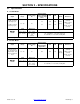
SECTION 2 − SPECIFICATIONS 2-1. Specifications A. 115 VAC Model Rated Welding Output Amperage Range Maximum OpenCircuit Voltage DC KVA KW Weight W/ Gun Overall Dimensions Length: 18-7/8 in (479 mm) 90 A @ 19 Volts DC, 20% Duty Cycle 30 − 135 20 2.90 2.50 15* 2.20* 1.
2-2. Duty Cycle And Overheating Duty Cycle is percentage of 10 minutes that unit can weld at rated load without overheating. If unit overheats, thermostat(s) opens, output stops, and cooling fan runs. Wait fifteen minutes for unit to cool. Reduce amperage or duty cycle before welding. C. 115 VAC Model 200 Output Amperes 135 Y Exceeding duty cycle can damage unit or gun and void warranty.
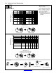
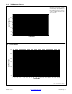
2-3. Volt-Ampere Curves The volt-ampere curves show the minimum and maximum voltage and amperage output capabilities of the welding power source. Curves of other settings fall between the curves shown. E. 115 VAC Model 30.0 OUTPUT VOLTS 25.0 20.0 Range 4 15.0 Range 3 Range 2 Range 1 10.0 5.0 0.0 0 10 20 30 40 50 60 70 80 90 100 110 120 130 140 150 160 LOAD AMPS F. 230 VAC Model 30.0 25.0 Range 4 OUTPUT VOLTS 20.0 Range 3 15.0 Range 2 Range 1 10.0 5.0 0.
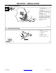
SECTION 3 − INSTALLATION 3-1. Installing Welding Gun 1 2 3 4 Loosen thumbscrew. Insert gun end through opening until it bottoms against drive assembly. Tighten thumbscrew. 4 2 Drive Assembly Gun Securing Thumbscrew Gun End 3 Gun Trigger Leads Insert leads, one at a time, through gun opening on front panel. Connect female friction terminals to matching male terminals in unit. Polarity is not important. Close door. 1 Ref. 802 440-A 3-2.
3-3. Process/Polarity Table Cable Connections Process Polarity Cable To Gun Cable To Work GMAW − Solid wire with shielding gas DCEP − Reverse polarity Connect to positive (+) output terminal Connect to negative (−) output terminal FCAW − Self-shielding wire − no shielding gas DCEN − Straight Polarity Connect to negative (−) output terminal Connect to positive (+) output terminal 3-4.
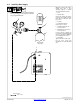
3-5. Installing Gas Supply Obtain gas cylinder and chain to running gear, wall, or other stationary support so cylinder cannot fall and break off valve. . DO NOT use Argon/Mixed gas regulator/flowmeter with CO2 shielding gas. See Parts List for optional CO2 gas regulator/flowmeter. 1 4 2 1 Cap 2 Cylinder Valve Remove cap, stand to side of valve, and open valve slightly. Gas flow blows dust and dirt from valve. Close valve. 3 Cylinder 4 Regulator/Flowmeter Install so face is vertical.
3-6. Selecting A Location And Connecting Input Power For 115 VAC Model 1 2 1 18 in (460 mm) Rating Label Grounded Receptacle A 115 volt, 20 ampere individual branch circuit protected by time-delay fuses or circuit breaker is required. 2 3 3 Plug From Unit Select extension cord of 14 AWG for up to 50 ft (15 m) or 12 AWG for 50 up to 200 ft (61 m). Y Special installation may be required where gasoline or volatile liquids are present − see NEC Article 511 or CEC Section 20.
3-7. Selecting A Location And Connecting Input Power For 230 VAC Model 1 Rating Label Supply correct input power. 2 3 Plug (NEMA 6-50P) Receptacle (NEMA 6-50R) Connect plug to receptacle. 4 18 in (457 mm) of space for airflow Line Disconnect Device See Section 3-8. 4 Y Special installation may be required where gasoline or volatile liquids are present − see NEC Article 511 or CEC Section 20. L1 Y Always connect grounding conductor first.
3-8. Electrical Service Guide For 230 VAC Model Input Voltage 230 Input Amperes At Rated Output 20 Max Recommended Standard Fuse Or Circuit Breaker Rating In Amperes 20 Min Input Conductor Size In AWG/Kcmil 14 Max Recommended Input Conductor Length In Feet (Meters) 66 (20) Min Grounding Conductor Size In AWG/Kcmil 12 Reference: 1996 National Electrical Code (NEC) S-0092-J 3-9.
3-10. Threading Welding Wire 1 2 3 4 5 6 Wire Spool Welding Wire Inlet Wire Guide Pressure Adjustment Knob Drive Roll Gun Conduit Cable Lay gun cable out straight. 4 6 Tools Needed: 1 2 3 5 . Hold wire tightly to keep it from unraveling. 4 in (102 mm) 6 in (150 mm) Open pressure assembly. Pull and hold wire; cut off end. Push wire thru guides into gun; continue to hold wire. . Use pressure indicator Tighten scale to set a desired drive roll pressure.
SECTION 4 − OPERATION 4-1. Controls 1 Voltage Switch The higher the selected number, the thicker the material that can be welded (see weld setting label in welding power source or Sections 4-2 and 4-3, as applicable). Do not switch under load. . Switch must “click” into detent position 1, 2, 3, 4, or purge for proper contact. 2 Voltage Switch - Purge “0” Position In purge position, fan runs but there is no weld output. 3 Wire Speed Control Use control to select a wire feed speed.
4-2. Weld Parameter Chart For 115 VAC Model Welding Guide Settings are approximate. Adjust as required. Thicker materials using proper technique, joint preparation, and multiple passes. Material Wire T ype, Being Welded and Polarity Setting Steel Flux Core E71T can be welded Suggested Shielding Gas 20−30 cfh Flow Rate No Shielding −1 1 Gas Required Good for Windy .035” (0.9 mm) Solid Wire C25 Gas Mixture .024” (0.
for 115 Volt Wire Welding Package Recommended V oltage and Wire Speed Settings for Thickness of Metal Being Welded. Number on Left of Slash is Voltage Setting / Number on Right of Slash is Wire Feed Setting. 22 gauge (.8 mm) −−− 18 gauge (1.2 mm) 16 gauge (1.6 mm) 1/8 inch (3.2 mm) 3/16 inch (4.
4-3. Weld Parameter Chart For 230 VAC Model Welding Guide Settings are approximate. Adjust as required. Thicker materials using proper technique, joint preparation, and multiple passes. Material Wire T ype, Being Welded and Polarity Setting Steel Flux Core E71T can be welded Suggested Shielding Gas 20−30 cfh Flow Rate No Shielding −1 1 Gas Required Good for Windy Diameter of Wire Being Used .030” (0.8 mm) .035” (0.9 mm) or Applications .045” (1.2 mm) Solid Wire C25 Gas Mixture .024” (0.
for 230 Volt Wire Welding Package Recommended V oltage and Wire Speed Settings for Thickness of Metal Being Welded. Number on Left of Slash is Voltage Setting / Number on Right of Slash is Wire Feed Setting. 22 gauge (.8 mm) 18 gauge (1.2 mm) 16 gauge (1.6 mm) 1/8 inch (3.2 mm) 3/16 inch (4.8 mm) 1/4 inch (6.
SECTION 5 − THEORY OF OPERATION 1 Circuit Breaker CB1 Protects unit from an over-current condition by opening primary power line. 2 Power Switch S1 Turns unit and fan motor FM on and off. 3 3 Fan Motor FM And Transformer Fan Motor FM And Transformer Controlled by power switch S1. Fan cools internal components, and transformer supplies control voltage to PC1. 4 5 4 Thermostat TP1 Gun Trigger Receptacle RC3 2 Power Switch S1 Thermostat TP1 If unit overheats, TP1 opens stopping all weld output.
10 9 11 Range Switch S2 13 Main Rectifier SR1 Main Transformer T1 Stablizer L1 12 Capacitor C1 14 Polarity Changeover Block 15 Wire Drive Motor Welding Wire (Electrode) Work AC Or DC Control Circuits Weld Current Circuit Handler 135 / 175 Return To Table Of Contents TM-944 Page 19
SECTION 6 − TROUBLESHOOTING 6-1. Troubleshooting Table . See Section 6-2 or 6-3 for test points and values and Section 9 for parts location. Trouble No weld output; wire does not feed; fan does not run. Remedy Secure power cord plug PLG1 in receptacle (see Section 3-6 or 3-7). Replace building line fuse or reset circuit breaker if open. Place Power switch S1 in On position (see Section 4-1). Reset power source circuit breaker if open (see Section 7-2). No weld output; wire does not feed; fan runs.
Trouble No weld output; wire feeds. Remedy Connect work clamp to get good metal-to-metal contact. Replace gun contact tip (see Section 7-5). Check thumbscrew securing gun end to feedhead adapter and tighten if necessary. Low weld output. Connect unit to proper input voltage or check for low line voltage. Place Voltage switch S2 in desired position (see Section 4-1). Low or erratic wire speed. Readjust weld parameter settings. Change to correct size drive roll. Readjust drive roll pressure.
6-2.
Voltage Readings Resistance Values b) Tolerance − ±10 % unless specified Wiring Diagram − see Section 8 V1 115 volts ac with power cord plugged in R1-R6 All values for T1 are less than 1 ohm V2 115 volts ac with Power switch S1 On R7 V3 24 volts ac with Power switch S1 On Less than 1 ohm at minimum position of Wire Speed control R1; 55k ohms at maximum position of Wire Speed control R1 V4 30 volts dc with Power switch S1 On R8 Less than 1 ohm V5 27 volts dc with gun trigger pressed R9 V6
6-3.
Voltage Readings Resistance Values b) Tolerance − ±10 % unless specified Wiring Diagram − see Section 8 V1 230 volts ac with power cord plugged in R1-R6 All values for T1 are less than 1 ohm V2 230 volts ac with Power switch S1 On R7 V3 24 volts ac with Power switch S1 On Less than 1 ohm at minimum position of Wire Speed control R1; 55k ohms at maximum position of Wire Speed control R1 V4 30 volts dc with Power switch S1 On R8 Less than 1 ohm V5 27 volts dc with gun trigger pressed R9 V6
6-4. Control Board PC1 Testing Information (115 VAC Model) Be sure plugs are secure before testing. See Section 6-5 for specific values during testing.
6-5.
6-6. Control Board PC1 Testing Information (230 VAC Model) Be sure plugs are secure before testing. See Section 6-7 for specific values during testing.
6-7.
SECTION 7 − MAINTENANCE 7-1. Routine Maintenance Y Disconnect power before maintaining. 3 Months Replace unreadable labels. Repair or replace cracked weld cable. Clean and tighten weld terminals. 6 Months Blow out or vacuum inside. During heavy service, clean monthly. Or 7-2. Overload Protection 1 Circuit Breaker CB1 CB1 protects unit from overload. If CB1 opens, unit shuts down. 1 Reset breaker. 802 441 7-3.
7-4. Changing Drive Roll Or Wire Inlet Guide 1 2 Inlet Wire Guide Securing Screw Inlet Wire Guide Loosen screw. Slide tip as close to drive rolls as possible without touching. Tighten screw. 1 3 3 2 4 Tools Needed: Stamped .024 Retaining Pin To secure drive roll, locate open slot and push drive roll completely over retaining pin, then rotate drive roll (1/4 turn) to closed slot. 4 .030/.035 Groove Drive Roll The drive roll consists of two different sized grooves.
7-6. Cleaning Or Replacing Gun Liner Tools Needed: Y Disconnect gun from unit. 8 mm / 10mm Remove nozzle, contact tip, adapter, gas diffuser, and wire outlet guide. Head Tube 8 mm 10 mm Remove liner. Lay gun cable out straight before installing new liner. To Reassemble Gun: Insert new liner. Install wire outlet guide so that 1/8 in (3 mm) of liner sticks out. Hand tighten outlet guide, and then tighten two full turns more. Blow out gun casing.
7-7. Replacing Switch And/Or Head Tube Y Turn Off welding power source /wire feeder and disconnect gun. 1 Remove handle locking nut. 3 2 Slide handle. Remove switch housing. Install new switch and connect leads (polarity is not important). Reassemble in reverse order. If replacing head tube, continue to end of figure. 4 Secure head tube in vice. 5 6 Loosen jam nut. Remove from vice and turn head tube out by hand. Hand-tighten head tube into cable connector.
SECTION 8 − ELECTRICAL DIAGRAMS . The circuits in this manual can be used for troubleshooting, but there might be minor circuit differences from your machine. Use circuit inside machine case or contact your distributor for further information.
194 324-C Figure 8-1. Circuit Diagram For 115 VAC Model Effective With Serial No.
194 325-A Figure 8-2. Circuit Diagram For 230 VAC Model Effective With Serial No.
196 637-A Figure 8-3. Wiring Diagram For 115 VAC Model Effective With Serial No.
196 655-A Figure 8-4. Wiring Diagram For 230 Model Effective With Serial No.
195 890-A Figure 8-5. Circuit Diagram For 115 VAC Model Control Board PC1 Effective With Serial No.
195 891-A Figure 8-6. Circuit Diagram For 230 VAC Model Control Board PC1 Effective With Serial No.
TM-944C October 2003 Handler 135 (500 414) Eff. w/Serial No. LB096205 Handler 175 (500 416) Eff. w/Serial No. LB075197 Processes MIG (GMAW) Welding Flux Cored (FCAW) Welding Description Arc Welding Power Source And Wire Feeder Handler 135 / 175 And H-10 Gun Visit our website at www.HobartWelders.
SECTION 9 − PARTS LIST 22 . Hardware is common and 19 15 24 41 42 43 45 47 46 52 51 48 1 44 49 39 34 40 31 2 50 33 32 36 38 37 35 3 4 30 5 6 7 8 28 29 9 10 11 27 12 13 26 25 17 23 16 14 18 20 21 not available unless listed. 802 449-E Figure 9-1.
Item No. Dia. Mkgs. Part No. Description Quantity Figure 9-1. Main Assembly . . . 1 . . . . . . . . . . . . . . . 199 566 . . . 2 . . . . . . . . . . . . . . . 196 006 . . . 3 . . . . . . . . . . . . . . . 211 887 . . . 4 . . . . . . . . . . . . . . . 204 608 . . . 5 . . . . . . . . . . . . . . . 202 998 . . . 6 . . . . . . . . . . . . . . . 203 072 . . . 7 . . . . . . . . . . . . . . . 211 339 . . . 8 . . . . . . . . . . . . . . . 202 726 . . . 9 . . . . . . . . . . . . . . . 195 886 . . . 9 . . . . .
Item No. Dia. Mkgs. Part No. Description Quantity Figure 9-1. Main Assembly (Continued) ... ... ... ... 41 42 43 44 ............... ............... ............... ............... 196 574 207 078 207 079 193 187 . . . 44 . . . . . . . . . . . . . . . 202 708 . . . 45 . . . . . . . . . . . . . . . 193 189 . . . 46 . . . . . . . . . . . . . . . 196 654 . . . . . . . . . . . . . . . . . . . . . 203 081 . . . 47 . . . . . . . . . . . . . . . 196 009 . . . 48 . . . . . . . . . . . . . . . 202 925 . . .
Figure 9-2. H-10 Gun Item No. Part No. Description 195 957 ... ... ... ... ... ... ... ... ... ... ... ... ... ... ... ... ... 1 2 2 2 2 3 4 5 6 7 8 9 9 9 9 10 11 . . . . . . . . . . . . . . . 169 715 . . . . . . . . . . . . . ♦087 299 . . . . . . . . . . . . . ♦000 067 . . . . . . . . . . . . . ♦000 068 . . . . . . . . . . . . . ♦000 069 . . . . . . . . . . . . . . . 169 716 . . . . . . . . . . . . . . . 170 470 . . . . . . . . . . . . . . . 169 718 . . . . . . . . . . . . . . . 169 738 . . . . . . .
Hobart Welding Products An Illinois Tool Works Company 600 West Main Street Troy, OH 45373 USA For Technical Assistance: Call1-800-332-3281 For Literature Or Nearest Dealer: Call 1-877-Hobart1 PRINTED IN USA 2003 Hobart Welding Products