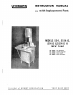
HOBART INSTRUCTION MANUAL «+s with Replacement Parts MODELS 5514, 5514-HS, 5514-D & 5514-D HS MEAT SAWS ML-18957 8514 {Painted) ML-18959 §514-HS (Painted} ML-18958 5514.D (SST) ML-18960 5514-D HS (SST} A product of HOBART CORPORATION TROY, OHIO 45374 FORM 11559A (Rev. 8.78) (Sups. £, 11559, 3.
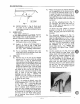
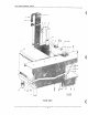
INSTRUCTIONS 5514 Y Fig 1 installation, Operation and Care of MODELS 5514, 5514-HS, 5514-D & 5514-D HS MEAT SAWS UNPACKING: Al Remove the shipping box that covers the saw. The following parts (which were disassembled for shipping purposes) should now be unpacked: table assembly, carriage assembly, carriage support assembly, saw blade, front wiper assembly, ear wiper assembly, switch push rod and feet. The pusher plate is packed in the scrap pan in the base compartment.
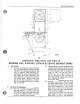
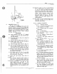
5614 INSTRUCTIONS B4 PL-11273 Fig. 2 (3, Fig. 3) must point to the right and downward when viewed from the front of the saw. If the teeth do not point downward, remove the blade, twist it inside out and replace it on the saw. Make sure the blade is properly placed in the upper guide unit (Fig. 2). Turn the tension adjustment hand wheel (8, Fig. 1) to the right until the figure “3” starts to show in the tension indicator (2, Fig. 4).
NOTE: Switch should always be assembled so that switch knob (11, Fig. 4) must be pulled to start machine. Do not re-assemble access panel until electrical connections have been made. WIRING: ., Electrical connections should be made by qualified workmen who will observe all applicable Safety Codes and the National Electrical Code. CHECK THE DATA ON THE NAME PLATE (10, Fig. 4) TO MAKE SURE THAT IT AGREES WITH YOUR ELECTRICAL SUPPLY BEFORE CONNECTING TO THE POWER LINE. A hole (8, Fig.
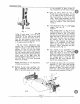
514 INSTRUCTIONS PL-7742 Fg5 D.5 SWITCH KNOB (11, Fig. 4): Knob must be pulled fo start machine. This eliminates chance starting by accidental bumping of knob. LUBRICATION: Very little lubrication is required, because all the high-speed shafts have either roller or ball bearings which are grease packed and will operate a long time without attention. E.1 Keep a small amount of grease in the six ball bearing rollers on the carriage. Apply a few drops of oil frequently to the Gage plate rack (4, Fig.
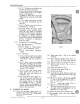
PL7683) Fig. 7 CLEANING & SANITIZING: This saw has been designed for quick and easy cleaning. It is IMPORTANT that any machine used for the preparation of food be kept in a clean and sanitary condition. Daily cleaning is recommended. Make sure saw is turned and stopped before starting cleaning operation. PROCEDURE: G.1 Turn (at either end) the “L” shaped carriage stop (Fig. 6) and roll off stainless steel carriage. .2 Rotate Gage plate (1, Fig. 4) to raised or vertical position. G.
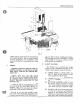
5514 INSTRUCTIONS G.13.1.2.7 Rinsing and sanitizing can be done in one of two ways: {a)Go over all cleaned surfaces with a cloth soaking wet in the “Fickleness” rinse solution, {b) Rinse in fresh water and apply “Mikro-Klene™ solution via of spray bottle. G.13.1.2.8 Allow all surfaces to drain dry and then re-assemble. Do not wipe dry. (.13.1.2.9 Protect saw {rom re-contamination by covering. G.13.1.2.10 Rinse the nylon brush thoroughly under running water.
RSN TS ADJUSTMENT OF BLADE BACK-UP BLOCK: Special TUNGSTEN CARBIDE blade backup blocks take the cutting thrust. They are located at the back edge of the saw blade, in the upper guide (Fig. 2) and the front lower wiper unit (Fig. 3). 1.1 Adjust the upper back-up block by turning screw (1, Fig. 2). J.2 Adjust the lower back-up block (7, Fig. 3) by muting screw Fig. 3).
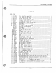
SULLY, PL-12235 PART NG, $116774-1 51167742 §C-10-13 SC-36-53 SC-21 PB-28 OWL-2 Wit $D24-29 P78917 RA78928 M68176 SC-1048 OWL-12 P78917 C102359 SC627 Wi347 A-102285 SC-62-53 B117664 ES-18.8 WL44 5C6243 D162523-1 D-1023232 $C82-38 Wilda NS-13-25 E-102380-1 E-102380-2 M68176 SC SC-88 M-23274 E-102313 5-78993-1 5789932 sC8238 WL4< NS-13-25 M4388.
REPLACEMENT PARTS 5514 HEAD UNIT ILLUS. PART PL-10866 NO. NAME OF PART AMT. . 1 8C21$ Mach. Screw #10-24 x 7/8° Phil. Flat PIECE Bracket Hinge -2 3 D1025ez Door Sub-says. (Head) 1 4 M20851 Screw Latch 1 5 M-20852 Latch 1 6 M-79686 Catch Friction 1 7 A1082242 Clanged Pulley (Blade) Sub-Says. Unit (Incas.
5514 REPLACEMENT PARTS MOTOR AND PULLEY UNIT ILLUS. PART PL-10731 NO. NAME OF PART AMT, 1 — Motor (see separate Motor Parts Sheet) NS419 Lock Nut “Slowpoke” 4 kg NS13-30 Full Nut Hex Fin. —4 ; prang OWLET Lock Washer 1/2” Int. Shake proof ES-8-30 Washer 4 *6 ES-830 NS13-30 Fall Nat Hex Fin. -4 i 8 A-103178 Seal -1 i 9 B-103205 Plate Wear SC6812 Mach. Resew #1032 x 5/16" Trimmed Hex A103178 B110S51 Groove-Pin Special A-108224-2 Clanged Pulley (Blade) Sub-Says. Unit (Incas.
i REPLACEMENT PARTS 5614 GAGE PLATE UNIT ill Us. PART PLB438 NO. NAME GF PART ANT. RI7958-1 Bracket Gage Plate Support (Rear) (Painted Mach.} 2 R77958.2 Bracket Gage Plate Support (Rear) (SST Mach.) 3 M35 En 4 P7I84S Spring Gage Plate 5 Sci-14 Mach, Screw ¥8-32 x 3/8" Rd. Hd. 6 WLl Lock Washer #8 x 0477 x 0317 — 7 B10386O Knob ’ B SC-1036 Set Screw #10-24 x 1/4” Soc. Hdqrs, Kn. Cup Pr. 9 MI7843 St aft « Worm o meteor e 10 M-83481 Worm Bracket & Bearing Sub-As.
REPLACEMENT PARTS 8614 TABLE, CARRIAGE AND TRACK UNIT ILLUS. PART PL-8373 NO. NAME OF PART AMT. 1 Pa787Ed Rustier Plate Says. — 1 2 RAISER Carriage Sub-Says. (Painted Mach) 1 3 RI79852 Carriage Sub-Says. (S5T Mach) — 1 4 NS13.25 Full Nut Hex Fin. 4 S Wild Lock Washer 3/8” x .136" x .070" + 6 WSW Washer Bali Bearing Nice #8070 4 8 5C3773 Fin. Bolt x 17 Hex Hd. 4 9 WS1814 Washer (3/64” thk) 2 : 10 Wsd3d2 Washer (010" the) As Reed.
REPLACEMENT PARTS 5514 UPPER GUIDE, GUARD AND PULLEY WIPER UNIT . ILLUS. PART i PL-11376 NO. NAME OF PART ANT, i 1 B102399 Upper Pulley Wiper Says. (uncles. items SC-53-1 Mach. Screw #10-24 x 1/4" Truss &101928 Wiper Upper Pulley PM39TL Guard Upper Guide Blade 1 i 5 SC-13 Mach. Screw #1024 x 3/8” Truss B113863 Upper Guide Support & Bushing Sub-Says. 1 i 7 S049-22 Set Strew x 7/8" Hals, Flat NS18-33 Yam Nut Hex Fin. -1 i 9 MIDDY Blade Back Up Block Sub-Says. M101925 Spring Back Up Block 50676 Mach.
REPLACEMENT PARTS 5514 LOWER WIPER AND GUIDE UNIT ILLUS. PART PL-11377 NO, NAME OF FART AMT. 1 al01928 Wiper Blade Saw Pulley 2 50534 Mach. Screw » #10-24 X 14" Truss Hd. 3 M101934 Bracket Scraper Pivot 4 SCREES Mach. Screw #8-32 x 3/16” Rd. Hd. 5 WL6el Lock Washer « #8 x .047" x 031" 6 Scar Fin. Bolt x 3/4” Hex Bd.
REPLACEMENT PARTS 5514 ELECTRICAL UNIT ILLUS. PART PL-12236 NO. NAME OF PART AMT, 39 AQ17124-1 Constructor & Screw Says. (208230 V., 60 Ha; 220 V., 50 Hz,, 3 Ph) (uncles. iem #41)— 40 AdI71242 Contractor & Screw Says. (113 V., 50/60 Hz., 3 Ph) (Pilot Herewith) {incl. fem #41) —— 41 SD520 Self-Tapping Screw #10-32 » 3/8” Phil, Pan H4. “Apatite” 42 D113861 Pabst Control 1 M86163-1 Knob » S Witch o i 2 M-B0538.