MODEL AM14F, AM14T, & AM14TC DISHWASHERS MODELS AM14F AM14T AM14TC ML-110975 ML-110973 ML-110974 701 S. RIDGE AVENUE TROY, OHIO 45374-0001 937 332-3000 www.hobartcorp.com FORM 34555 (Dec.
POST IN A PROMINENT LOCATION THE INSTRUCTIONS TO BE FOLLOWED IN THE EVENT THE SMELL OF GAS IS DETECTED. THIS INFORMATION CAN BE OBTAINED FROM THE LOCAL GAS SUPPLIER. IMPORTANT IN THE EVENT A GAS ODOR IS DETECTED, SHUT DOWN UNIT(S) AT MAIN SHUTOFF VALVE AND CONTACT THE LOCAL GAS COMPANY OR GAS SUPPLIER FOR SERVICE. FOR YOUR SAFETY DO NOT STORE OR USE GASOLINE OR OTHER FLAMMABLE VAPORS OR LIQUIDS IN THE VICINITY OF THIS OR ANY OTHER APPLIANCE.
TABLE OF CONTENTS GENERAL ............................................................... 4 INSTALLATION . . . . . . . . . . . . . . . . . . . . . . . . . . . . . . . . . . . . . . . . . . . . . . . . . . . . . . . . . . . . . . 5 UNPACKING . . . . . . . . . . . . . . . . . . . . . . . . . . . . . . . . . . . . . . . . . . . . . . . . . . . . . . . . . . . 5 INSTALLATION CODES . . . . . . . . . . . . . . . . . . . . . . . . . . . . . . . . . . . . . . . . . . . . . . . . . . 5 LOCATION . . . . . . . . . . .
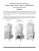
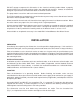
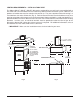
Installation, Operation, and Care of MODEL AM14F, AM14T, AM14TC DISHWASHERS SAVE THESE INSTRUCTIONS GENERAL The AM14T, AM14TC, and AM14F dishwashers are semi-automatic rack-type machines. On model AM14T (Fig. 1) the doors open on opposite sides of the machine allowing the rack to move straight through. Model AM14TC can be located in a corner; adjacent doors open so the rack moves in and out at a 90° angle. Model AM14F (Fig.
DO NOT attempt to operate this dishwasher in the chemical sanitizing mode without a properly installed, NSF-listed, chemical sanitizer feeder (not supplied with machine). Contact an authorized detergent representative for information about a chemical sanitizer feeder. The pump motor is rated 2HP and has thermal overload protection. The fill line incorporates an atmospheric vacuum breaker to prevent any reverse flow of water from the dishwasher into the potable water supply.
On models AM14T and AM14TC, dish tables should be turned down and fitted into the dishwasher (Fig. 2). Use an NSF approved sealer between table and tank lip to prevent leakage. Fasten the tables to the tank lip with truss head screws. Dish tables are not required with model AM14F. High-temperature or gas heat dishwashers will probably require a hood or vent over the dishwasher in order to meet local codes.
WATER CONNECTION A suitable water hammer arrestor should be installed in the water line just ahead of the dishwasher. Without Electric or Gas Booster Water Heater The water supply line is connected to the line strainer (Fig. 1) with 3/4" pipe. A manual shut off valve and pipe union are required.
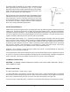
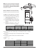
Static inlet gas pressure should not exceed 14" W.C. for either natural or propane gas. The minimum value is for purpose of input adjustment. The gas valve (Fig. 3) is provided with a pressure tap to measure the gas pressure downstream, which is also the manifold pressure. Gas supply piping must have a sediment trap (supplied by others) installed ahead of the dishwasher's gas control (Fig. 3). Gas Valve NOTE: DO NOT use Teflon tape on gas line pipe threads.
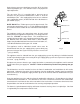
VENTING REQUIREMENTS — WITH GAS TANK HEAT The Hobart AM14F / AM14T / AM14TC dishwasher equipped for gas tank heat is not provided with a flue collar and is not intended to have the flue directly connected to a ventilation system. However, the products of combustion must be vented to the outside air. The most common method of venting is a vent hood over the entire dishwasher (Fig. 4). Refer to Rate of Exhaust Flow Calculations on the next page for calculations of the proper vent rate for your hood.
➤ ➤ CLEARANCE HEIGHT ➤ NOTE: Any listed and labeled factory-built commercial exhaust hood tested in accordance with UL Standard 710 by a nationally recognized testing laboratory, should be installed according to the terms of its listing and the manufacturer's installation instructions. ➤ LENGTH ➤ RATE OF EXHAUST FLOW CALCULATIONS Based on the 1996 International Mechanical Code. The Rate of air flow required for a vent hood is calculated using the following definitions (Fig.
ELECTRICAL CONNECTIONS WARNING: ELECTRICAL AND GROUNDING CONNECTIONS MUST COMPLY WITH THE APPLICABLE PORTIONS OF THE NATIONAL ELECTRICAL CODE AND/OR OTHER LOCAL ELECTRICAL CODES. WARNING: DISCONNECT ELECTRICAL POWER SUPPLY AND PLACE A TAG AT THE DISCONNECT SWITCH TO INDICATE THAT YOU ARE WORKING ON THE CIRCUIT. Refer to the wiring diagram attached inside the control box and to the machine data plate for service size requirements when connecting the dishwasher.
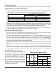
ELECTRICAL DATA Model Volts / Hz / Ph Minimum Circuit Ampacity Maximum Protective Device AMPS Tank Heat Dishwasher ONLY Electric 60 Gas 20 Optional 13 KW Electric Booster ONLY 208 - 240 / 60 / 1 AM14T AM14TC 208 / 60 / 1 Electric 80 240 / 60 / 1 Electric 80 Electric 30 Gas 15 208 - 240 / 60 / 3 AM14F 208 / 60 / 3 Electric 50 240 / 60 / 3 Electric 50 Electric 15 Gas 15 25 480 / 60 / 3 Compiled in accordance with the National Electrical Code, ANSI / NFPA 70 (latest edition)
DETERGENT, RINSE AID, OR SANITIZER DISPENSERS — Tubing Installation All detergent, rinse aid, and / or sanitizer dispensers must have all connections sealed against leakage. The dishwasher uses 1.42 gallons per rack at a flow rate of 5.67 gallons per minute at 20 psig flowing pressure (equivalent to a maximum head pressure of 46 feet of water). This information is used when setting the detergent, rinse aid, or sanitizer pumps.
OPTIONAL EQUIPMENT CONNECTIONS — Detergent, Rinse Aid, Sanitizer Dispensers WARNING: ELECTRICAL AND GROUNDING CONNECTIONS MUST COMPLY WITH THE APPLICABLE PORTIONS OF THE NATIONAL ELECTRICAL CODE AND/OR OTHER LOCAL ELECTRICAL CODES. WARNING: DISCONNECT ELECTRICAL POWER SUPPLY AND PLACE A TAG AT THE DISCONNECT SWITCH TO INDICATE THAT YOU ARE WORKING ON THE CIRCUIT. Detergent Dispenser (Fig. 10) Terminals DPS1 and DPS2 are supplied with controlled machine line voltage.
OPERATION PREPARATION Place the pump strainer (when equipped), overflow tube, overflow cover, end cover, slanted strainer, and the strainer bucket in their respective positions (Fig. 11). An automatic detergent dispenser is recommended. Closely follow supplier’s instructions. If no automatic dispenser is used, scatter the initial charge of detergent on the slanted strainer. Replenish as needed. Fig. 11 Open the manual gas valve (if applicable). Close the door(s) which automatically closes the drain.
DISHWASHING Scrape the dishes to remove large particles of food and debris. Never use steel wool on ware to be loaded into the dishmachine. Fig. 14 Place the dishes in a rack so water has free access to all sides of every dish. Stand plates and dishes up edgewise in a peg-type rack (Fig. 14). Cups, glasses, and bowls should be inverted in an open-type or compartment type rack (Fig. 14). Silverware and other small pieces may be scattered loosely over the bottom of a flat-bottom rack.
CLEANING The machine must be thoroughly cleaned at the end of each working shift or at least daily. Never use steel wool to clean warewasher surfaces. Use only products formulated to be safe on stainless steel. Turn off the power switch. Open the machine door(s). Clean off the dish tables into the dishwasher. Drain the machine by pulling the drain lever (Fig. 11). Remove and empty the slanted strainer and strainer bucket. Wash and rinse them thoroughly. Raise the overflow cover and remove the overflow tube.
MAINTENANCE WARNING: DISCONNECT ELECTRICAL POWER SUPPLY (BOTH DISHWASHER AND BOOSTER IF APPLICABLE) AND PLACE A TAG(S) AT THE DISCONNECT SWITCH(ES) TO INDICATE THE CIRCUIT(S) ARE BEING WORKED ON BEFORE BEGINNING ANY MAINTENANCE PROCEDURE. Wash Arms Upper and lower wash and rinse arms (Figs. 15, 16) should turn freely and continue turning for a few seconds after being whirled by hand.
TROUBLESHOOTING Manual Reset Button on Pump Motor The motor is equipped with a gray manual reset button near the end cover of the motor. If the pump motor becomes overheated, the thermal overload protector will cause the motor to not operate. If this occurs, press the power switch OFF and allow the motor to cool. Then press the gray manual reset button, press the power switch ON, and resume normal operation. To avoid a service call, check symptoms and related possible causes.
SYMPTOM POSSIBLE CAUSE Inadequate rinse or rinse water temperature is too low. 1. Dirty line strainer causing reduced water flow. Turn off water supply, remove strainer cap, withdraw and clean screen. Reassemble. 2. Low supply line pressure. 3. Excessive mineral deposits throughout wash and rinse system. Deliming may be necessary. 4. Incoming water temperature to booster (if applicable) below 110°F. Extend wash cycle from 40 to 60 seconds. 1. Foreign material preventing proper valve operation.