OM-353 122200U November 2000 Processes TIG (GTAW) Welding Stick (SMAW) Welding Description Arc Welding Power Source Cybertig
From Hobart to You Thank you and congratulations on choosing Hobart. Now you can get the job done and get it done right. We know you don’t have time to do it any other way. This Owner’s Manual is designed to help you get the most out of your Hobart products. Please take time to read the Safety precautions. They will help you protect yourself against potential hazards on the worksite. We’ve made installation and operation quick and easy.
TABLE OF CONTENTS WARNING This product, when used for welding or cutting, produces fumes or gases which contain chemicals known to the State of California to cause birth defects and, in some cases, cancer. (California Health & Safety Code Section 25249.5 et seq.) The following terms are used interchangeably throughout this manual: TIG = GTAW Stick = SMAW SECTION 1 – SAFETY PRECAUTIONS - READ BEFORE USING . . . . . . . . . . . . . . . . . . . . . . . . . . . . 1-1. Symbol Usage . . . . . . . . . . . . . .
SECTION 1 – SAFETY PRECAUTIONS - READ BEFORE USING som _nd_4/98 1-1. Symbol Usage Means Warning! Watch Out! There are possible hazards with this procedure! The possible hazards are shown in the adjoining symbols. Y Marks a special safety message. . Means “Note”; not safety related. This group of symbols means Warning! Watch Out! possible ELECTRIC SHOCK, MOVING PARTS, and HOT PARTS hazards. Consult symbols and related instructions below for necessary actions to avoid the hazards. 1-2.
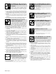
ARC RAYS can burn eyes and skin. Arc rays from the welding process produce intense visible and invisible (ultraviolet and infrared) rays that can burn eyes and skin. Sparks fly off from the weld. D Wear a welding helmet fitted with a proper shade of filter to protect your face and eyes when welding or watching (see ANSI Z49.1 and Z87.1 listed in Safety Standards). D Wear approved safety glasses with side shields under your helmet.
1-3. Additional Symbols For Installation, Operation, And Maintenance FIRE OR EXPLOSION hazard. MOVING PARTS can cause injury. D Do not install or place unit on, over, or near combustible surfaces. D Do not install unit near flammables. D Do not overload building wiring – be sure power supply system is properly sized, rated, and protected to handle this unit. D Keep away from moving parts such as fans. D Keep all doors, panels, covers, and guards closed and securely in place.
1-5. EMF Information Considerations About Welding And The Effects Of Low Frequency Electric And Magnetic Fields Welding current, as it flows through welding cables, will cause electromagnetic fields. There has been and still is some concern about such fields.
SECTION 1 – CONSIGNES DE SECURITE – LIRE AVANT UTILISATION som _nd_fre 4/98 1-1. Signification des symboles Signifie Mise en garde ! Soyez vigilant ! Cette procédure présente des risques de danger ! Ceux-ci sont identifiés par des symboles adjacents aux directives. Y Identifie un message de sécurité particulier. . Signifie NOTA ; n’est pas relatif à la sécurité.
LES RAYONS DE L’ARC peuvent provoquer des brûlures dans les yeux et sur la peau. Le rayonnement de l’arc du procédé de soudage génère des rayons visibles et invisibles intenses (ultraviolets et infrarouges) susceptibles de provoquer des brûlures dans les yeux et sur la peau. Des étincelles sont projetées pendant le soudage. D Porter un casque de soudage muni d’un écran de filtre approprié pour protéger votre visage et vos yeux pendant le soudage ou pour regarder (voir ANSI Z49.1 et Z87.
1-3. Dangers supplémentaires en relation avec l’installation, le fonctionnement et la maintenance Risque D’INCENDIE OU D’EXPLOSION. DES ORGANES MOBILES peuvent provoquer des blessures. D Ne pas placer l’appareil sur, au-dessus ou à proximité de surfaces infllammables. D Rester à l’écart des organes mobiles comme le ventilateur. D Maintenir fermés et fixement en place les portes, panneaux, recouvrements et dispositifs de protection.
1-4. Principales normes de sécurité Safety in Welding and Cutting, norme ANSI Z49.1, de l’American Welding Society, 550 N.W. Lejeune Rd, Miami FL 33126 Safety and Health Sandards, OSHA 29 CFR 1910, du Superintendent of Documents, U.S. Government Printing Office, Washington, D.C. 20402. Recommended Safe Practice for the Preparation for Welding and Cutting of Containers That Have Held Hazardous Substances, norme AWS F4.1, de l’American Welding Society, 550 N.W.
SECTION 2 – DEFINITIONS 2-1. Warning Label Definitions Warning! Watch Out! There are possible hazards as shown by the symbols. 1 1.1 1.2 1.3 2 1 1.1 2.1 1.3 1.2 2.2 2.3 3 2 2.1 2.2 3.1 2.3 3.2 3 3.1 3.2 3.3 3.3 4 4.1 4 4.1 + + 5 + 6 5 Electric shock from welding electrode or wiring can kill. Wear dry insulating gloves. Do not touch electrode with bare hand. Do not wear wet or damaged gloves. Protect yourself from electric shock by insulating yourself from work and ground.
2-2. Rating Label For CE Products 1 1 U0 = 80V U0 = 80V ISO/IEC 974-1 7A/10.2V 310A/22.4V X 25% 60% I2 310A 200A 155A U2 22.4V 18V 100% 16.2V 5A/20.2V 310A/32.4V X 25% 60% I2 310A 200A 155A U2 32.4V 28V 100% 26.2V 1 U1 = 220 50 Hz U1 = 380 I1max = 117.2A I1Eff = 59A U1 = 415 I1max = 63.8A I1Eff = 32A I1max = 72.
2-3. Symbols And Definitions NOTE A V Some symbols are found only on CE products.
SECTION 3 – INSTALLATION 3-1. Specifications Rated Welding Output NEMA Class II (40) – 250 Amperes, 30 Volts AC, 40% Duty Cycle Amperes Input at AC Balanced Rated Load Output, 50/60 Hz, Single-Phase PFC** 200 V 230 V 460 V 575 V KVA KW No PFC 106 (4.6*) 92 (4*) 46 (2*) 37 (1.6*) 21 (0.89*) 11.4 (0.68*) With PFC 76 66 33 26 15.2 11.
3-3. Duty Cycle And Overheating Duty Cycle is percentage of 10 minutes that unit can weld at rated load without overheating. If unit overheats, thermostat opens, output stops, light goes on (CE models only), and cooling fan runs. Wait fifteen minutes for unit to cool. Reduce amperage or duty cycle before welding. Y Exceeding duty cycle can damage unit and void warranty.
3-4. Selecting A Location 1 2 Lifting Eye Lifting Forks Use lifting eye or lifting forks to move unit. Movement If using lifting forks, extend forks beyond opposite side of unit. 1 3 4 OR 2 Location And Airflow Rating Label (Non CE Models Only) Rating Label (CE Models Only, See Section 2-2) Use rating label to determine input power needs. CE label located on rear panel. 5 6 6 Plate Label (CE Models Only) Line Disconnect Device Locate unit near correct input power supply.
3-6. Tipping Y Be careful when placing or moving unit over uneven surfaces. 3-7. Weld Output Terminals And Selecting Cable Sizes Y ARC WELDING can cause Electromagnetic Interference. To reduce possible interference, keep weld cables as short as possible, close together, and down low, such as on the floor. Locate welding operation 100 meters from any sensitive electronic equipment. Be sure this welding machine is installed and grounded according to this manual.
3-8. Remote 14 Receptacle Socket* A B K Socket Information A 24 volts ac. B Contact closure to A completes 24 volts ac contactor control circuit. C Command reference; 0 to +10 volts dc output to remote control. D Remote control circuit common. E 0 to +10 volts dc input command signal from remote control. K Chassis common. J I H C L N D M G E F A ST-154 795-C *The remaining sockets are not used. 3-9.
3-10. Electrical Service Guide NOTE All values calculated at 60% duty cycle.
3-11. Placing Jumper Links And Connecting Input Power Check input voltage available at site. 1 200 VOLTS L 230 VOLTS L 460 VOLTS L L L Y Only make connections for the voltages shown on the label inside your unit. Do not make connections for any other voltages. If jumper link label is missing from inside unit, check rating label (see Section 3-4) for allowable input voltages.
SECTION 4 – OPERATION 4-1. Controls 1 7 8 2 9 Voltmeter See Section 4-3. 3 6 Ammeter See Section 4-3. High Frequency Switch See Section 4-11. 10 4 11 12 Output (Contactor) Switch See Section 4-8. 5 5 13 Spot Time Switch And Control (Optional) See Section 4-5. 6 Preflow Time Control (Optional) See Section 4-12. 4 3 7 AC Balance Control See Section 4-6. 8 Crater Time Control And Switch See Section 4-4. 14 9 Amperage Adjustment Control And Switch See Section 4-7.
4-2. Output Selector Switch 1 Output Selector Switch Y Do not use AC output in damp areas, if movement is confined, or if there is danger of falling. Use AC output ONLY if required for the welding process, and then use a remote control. 1 Y Do not change position of switch while welding or while under load. Use switch to select (DCEN) Direct Current Electrode Negative, AC, or (DCEP) Direct Current Electrode Positive output without changing weld output cable connections. Ref. ST-181 675-A 4-3.
4-4. Crater Time Controls 1 1 Crater Time Control Use control to reduce current over a set period of time (0–15 seconds) at the end of the weld cycle when NOT using a remote current control. 2 Crater Time Switch ON – provides crater time. OFF – provides no crater time. Place switch in the OFF position for Shielded Metal Arc Welding (SMAW).
4-6. AC Balance Control 1 AC Balance Control Balance Control (AC GTAW): Control changes the AC output square wave. Rotating the control towards 10 provides deeper penetration. Rotating the control towards 0 provides more cleaning action of the workpiece. 1 When the control is in the Balanced position, the wave shape provides equal penetration and cleaning action. Application: When welding on oxide forming materials such as aluminum or magnesium, excess cleaning is not necessary.
4-7. Amperage Adjustment Controls 1 1 Amperage Adjustment Control Use control to adjust amperage, and preset amperage on ammeter (see Section 4-3). This control may be adjusted while welding. For remote amperage control, front panel control setting is the maximum amperage available. For example: If front panel control is set to 200 A, the range of the remote amperage control is 5 to 200 A. For spot welding, use Amperage Adjust control to select from 5–310 amps of peak amperage (see Section 4-5).
4-9. Arc Controls 1 Arc Control (Dig) For AC And DC SMAW Welding 1 When set at 0, short-circuit amperage at low arc voltage is the same as normal welding amperage. When setting is increased, shortcircuit amperage at low arc voltage increases. Set at 0 for GTAW welding. 2 2 Arc Control Switch Place switch in the ON position to turn on arc control circuitry. When switch is in the OFF position, no additional amperage is available at low arc voltages.
4-11. High Frequency Controls Y Place High Frequency switch in Off position before using the shielded metal arc welding (SMAW) process. 1 1 High Frequency Switch START – (Up position) provides HF for arc starting only. High frequency turns on to help start arc when output is enabled. High frequency turns off when arc is started, and turns on whenever arc is broken to help restart arc. Application: HF Start is used when the DCEN GTAW process is required. OFF – provides no HF.
SECTION 5 – MAINTENANCE & TROUBLESHOOTING 5-1. Routine Maintenance Y Disconnect power before maintaining. 3 Months Clean And Tighten Weld Terminals Repair Or Replace Cracked Weld Cables Replace Unreadable Labels Adjust Spark Gaps Replace Cracked Parts 14-Pin Cord Torch Cable Gas Hose 6 Months OR Blow Out Or Vacuum Inside, During Heavy Service, Clean Monthly 5-2.
5-3. Adjusting Spark Gaps Y Turn Off power before adjusting spark gaps. Open access door. 1 4 4 2 3 Spark Gap Normal spark gap is 0.008 in (0.203 mm). 3 2 Tungsten End Of Point Replace point if tungsten end disappears; do not clean or dress tungsten. If adjustment is needed, proceed as follows: 1 3 Adjustment Screws Loosen screws. Place gauge of proper thickness in spark gap. 4 Pressure Point Apply slight pressure at point until gauge is held firmly in gap.
Trouble Fan not operating. NOTE: fan only runs when cooling is necessary. Remedy Check and remove anything blocking fan movement. Have Factory Authorized Service Agent check fan motor. Unit provides only maximum or minimum weld output. Have Factory Authorized Service Agent check control board PC1. Weld output always above or always below set value. Have Factory Authorized Service Agent check control board PC1 and hall device HD1. Erratic or improper weld output.
5-5.
SECTION 6 – HIGH FREQUENCY (HF) 6-1. Welding Processes Using HF 1 HF Voltage GTAW – helps arc jump air gap between torch and workpiece and/ or stabilize the arc. SAW – helps arc reach workpiece through flux granules. 2 1 2 1 Work Work Gas Tungsten Arc Welding (GTAW) Submerged Arc Welding (SAW) Flux high_freq1 7/95 – S-0693 6-2.
6-3. Correct Installation 6 Weld Zone 50 ft (15 m) 50 ft (15 m) 4 1 5 2 7 3 7 Ground All Metal Objects And All Wiring In Welding Zone Using #12 AWG Wire Nonmetal Building Ground Workpiece If Required By Codes 8 7 7 10 Metal Building 9 Ref. S-0695 / Ref. S-0695 1 HF Source (Welder With Built-In HF Or Separate HF Unit) Ground metal machine case, work output terminal, line disconnect device, input supply, and worktable.
16 23 29–Fig.7–2 1 28 2–Fig.7–3 5 6 27 3 4 7–Fig.7–5 8 26 25 9 24 10 22 11 12 15 14 31 30 13 21 20 19 17–Fig.7–4 18 SECTION 7 – PARTS LIST . Hardware is common and not available unless listed. OM-353 Page 32 ST-120 135-R Figure 7-1.
Replace Coils at Factory or Authorized Factory Service Station Item No. Dia. Mkgs. Part No. Description Quantity Figure 7-1. Main Assembly . . 1 . . . . . . . . . . . . . . 182 605 . . 2 . . . . SR1 . . . . . 181 106 . . 3 . . . . . S4 . . . . . 133 061 . . . . . . . . PLG10 . . . 164 899 . . . . . . . . PLG11 . . . . 168 809 . . 4 . . . . . . . . . . . . . . 057 357 . . 5 . . . . . . . . . . . . . . 010 494 . . 6 . . . . . . . . . . . . . . 134 201 . . 7 . . . . . . . . . . . . . . . Fig 7-5 . . 8 .
. Hardware is common and 8 not available unless listed. 9 10 2 4 1 5 6 7 3 4 12 13 Includes Item 26 11 14 29 28 27 15 1 16 26 25 24 23 17 22 18 Fig 7-6 19 21 20 ST-120 088-G Figure 7-2.
Item No. Dia. Mkgs. Part No. Description Quantity Figure 7-2. Panel, Front w/Components (Fig 7-1 Item 29) . . 1 . . . . . . . . . . . . . . 097 922 . . KNOB, pointer . . . . . . . . . . . . . . . . . . . . . . . . . . . . . . . . . . . . . . . . . . . . . . . . . . . . 2 . . . . . . . . . . . . . . . . . . . . . . . . . NAMEPLATE, (order by model and serial number) . . . . . . . . . . . . . . . . . . . . . 3 . . . . . . . . . . . . . . 109 013 . . BUSHING, snap-in nyl .375 ID x .562mtg hole . . . . . .
Item No. Dia. Mkgs. Part No. Description 181 106 . . 1 . . . C7-10 . . . . 031 689 . . 2 . . . . . . . . . . . . . . 166 667 . . 3 . . . . . D1 . . . . . 037 956 . . 4 . . . . TP3 . . . . . 168 898 . . 5 . . SCR1-4 . . . . 115 114 . . 6 . . . . . . . . . . . . . . 173 714 . . . . . . . . . . . . . . . . . . . 028 516 . . . . . . . . PLG53 . . . . 115 092 Quantity Figure 7-3. Rectifier, Si Diode (Fig 7-1 Item 2) .. .. .. .. .. .. .. .. CAPACITOR, rectifier . . . . . . . . . . . . . . . . . . . . . . .
Item No. Dia. Mkgs. Part No. Description Quantity Figure 7-5. Panel, Mtg Components (Fig 7-1 Item 7) . . 1 . . . . . R7 . . . . . 186 468 . . 2 . . . . . . . . . . . . . . . 117 721 . . 3 . . . CR2,6 . . . . . 110 386 . . 4 . . . . . 2T . . . . . 072 253 . . 5 . . . SR2,3 . . . . 035 704 . . 6 . . . SN1,2 . . . . . 118 625 . . 7 . . . . . R6 . . . . . . 117 803 . . 8 . . . . C20 . . . . . . 119 834 . . 9 . . . . . 1T . . . . . . 117 372 . . . . . . . . . . . . . . . . . . . 108 023 . . 10 . . . CR5 . .
. Hardware is common and 15 not available unless listed. 14 17 5 16 13 3 6 2 4 7 11 8 1 9 10 18 23 22 19 21 20 ST-120 003-Q Figure 7-6.
Item No. Dia. Mkgs. Part No. Description Quantity Figure 7-6. Control Panel, Lower Front (Fig 7-2 Item 18) .. 1 .............. . . 2 . . . . R25 . . . . . . . 3 . . . . C14 . . . . . . . 4 . PC2, RC1 . . . . . . . . . . PLG21 . . . . . 5 . . . . . C6 . . . . . . . 6 . . . PLG3 . . . . . . 7 . . . . RC2 . . . . . . . 8 . . . . C15 . . . . . . . 9 . . . . CB1 . . . . . . . 10 . . . R13 . . . . . . . 11 . . . . G . . . . . . ................... ................... ................... . . 13 . . . . . . .
Notes OM-353 Page 40
Effective January 1, 2000 (Equipment with a serial number preface of “LA” or newer) This limited warranty supersedes all previous Hobart warranties and is exclusive with no other guarantees or warranties expressed or implied. Warranty Questions? Call 1-877-HOBART1 for your local Hobart distributor. Service You always get the fast, reliable response you need. Most replacement parts can be in your hands in 24 hours.
Owner’s Record Please complete and retain with your personal records. Model Name Serial/Style Number Purchase Date (Date which equipment was delivered to original customer.) Distributor Address City State Zip Resources Available Always provide Model Name and Serial/Style Number. To locate a Distributor, retail or service location: Contact your Distributor for: Welding Supplies and Consumables Call 1-877-Hobart1 or visit our website at www.HobartWelders.