I N S TR U C TI D SERIES REACH-INS O N S D SERIES REACH-IN REFRIGERATORS & FREEZERS 701 S. RIDGE AVENUE TROY, OHIO 45374-0001 937 332-3000 www.hobartcorp.com FORM 18261 Rev. E (Jan.
Installation, Operation and Care of D SERIES REACH-IN REFRIGERATORS & FREEZERS SAVE THESE INSTRUCTIONS GENERAL D Series Reach-In Refrigerators (38°F) and Freezers (0°F) may be ordered as one-, two-, or threesection cabinets. Doors may be full height or half height solid with stainless exterior surface and ABS plastic interior surface. Glass doors, full height or half height, are available for refrigerators only. High Capacity refrigeration systems are included with glass door units.
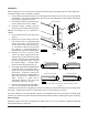
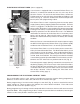
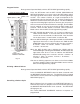
ASSEMBLY Some components can be removed to allow the cabinet to pass through short or narrow doorways. The door handle can be removed as follows: 1. If the adhesive-backed trim pieces are damaged during removal, new ones can be purchased from Hobart. The adhesive-backed trim pieces on the top and bottom of the handles need to be peeled off to expose the screws. 2. Peel off the trim pieces and remove the screws which secure the handles. FRONT TRIM PANEL UPPER HINGE 3.
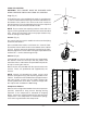
LEGS OR CASTERS WARNING: THE CABINET MUST BE BLOCKED AND STABLE BEFORE INSTALLING LEGS OR CASTERS. THREADED HOLE Legs (Fig. 4) To install the legs, raise and block the reach-in a minimum of 7" from the floor and thread the legs into the threaded holes on the bottom of the cabinet. The unit must be level in order to operate properly. Turn the adjustable feet in or out as required to level the unit front-to-back and side-to-side.
Condensate Evaporator D Series units are equipped with an automatic condensate evaporator that requires no drain connection. ELECTRICAL CONNECTIONS (Cord Connected Reach-Ins) 120Volt, 60 Hertz, 1 Phase WARNING: THIS MACHINE IS PROVIDED WITH A THREE-PRONGED GROUNDING PLUG. THE OUTLET TO WHICH THIS PLUG IS CONNECTED MUST BE PROPERLY GROUNDED. IF THE RECEPTACLE IS NOT THE PROPER GROUNDING TYPE, CONTACT AN ELECTRICIAN.
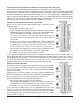
ELECTRONIC DEFROST TIMER (when equipped) If your freezer is equipped with an electronic Defrost Timer, it is located in a control box behind the trim rail at the top of the Reach-In Freezer. To access the the Defrost Timer, remove the Thumbscrew on the left side of the Control Box and slide the Lid to the left (Fig. 8). Save the Thumbscrew and Lid and put them back in place after programming is done. THUMBSCREW LID CONTROL BOX PL-41628-1 Fig.
To Change the Defrost Duration and Bypass the Setting of the Time Clock Begin with the SET CLOCK light blinking rapidly, indicating normal Operation Mode . . . If you want to change the Defrost Duration but not reset the time-of-day, press and hold the PROGRAM button for about 3 seconds until the PROGRAM light starts blinking. Release the PROGRAM button and the PROGRAM light and the SET CLOCK light remain lit. Press and hold the PROGRAM button again until the DEFROST ON light starts blinking.
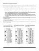
How to Set a Custom Defrost Schedule Begin with the defrost timer on normal Operation Mode: The SET CLOCK light is blinking rapidly and the PROGRAM and DEFROST ON lights are off. If all switches are OFF (Fig. 12), the factory preset defrost schedule is enabled: 2 AM, 8 AM, 2 PM, 8 PM. • Determine your own best defrost schedule. The upper set of switches represents the AM hours; the lower switches represent the PM hours. Allow a minimum of 2 hours between the start of any two defrost cycles.
Program Review During normal Operation Mode, with the SET CLOCK light blinking rapidly . . . Current Clock Time = HH:MM # Blinks = HH # Blinks (times 5) = MM Press the SET button until the SET CLOCK, PROGRAM and DEFROST ON lights are lit; then release the SET button and all three lights go off for two seconds. After that, all three lights begin to blink. The number of blinks of a light corresponds to the programmed value for that light (Fig. 15).
If the Defrost Timer's Battery Loses Power If the SET CLOCK, PROGRAM and DEFROST ON lights are all blinking (Fig. 15), the backup power supply (battery) to the Defrost Timer has weakened. Estimated battery life is 10 years. The timer can continue to function normally after the battery has weakened if the timer is reprogrammed. If a power outage occurs and is later restored after the battery has weakened, the following three things happen: • The defrost clock resumes as if it were 12:00 midnight.
DEFROST TIMER — Freezer units built between 1991 and 1997 were equipped with a defrost timer (Fig. 16) preset for four 23 – 25 minute defrost cycles per day (every 6 hours). By inserting a screwdriver into the large hole in the bracket and turning clockwise, the time of day that these cycles occur may be adjusted. MECHANICAL DEFROST TIMER — (Freezers built from 1997 to 2001) — When power is initially applied to the cabinet, the exterior dial of the defrost time clock (Fig.
MAINTENANCE CLEANING Cabinet Clean the inside of the cabinet and the doors weekly with a warm water solution of mild household liquid dishwashing detergent (such as Palmolive green or Ivory). Do not use anything containing grit, abrasive materials, bleach or harsh chemicals. Be cautious with new or improved formulas; use only after being well tested. Rinse thoroughly and dry with a clean soft cloth.