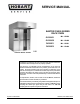
SERVICE MANUAL BAXTER OV500 SERIES RACK OVEN OV500G1 ML- 132500 OV500G2 ML- 132498 OV500E1 ML- 132501 OV500E2 ML- 132499 OV500G2 MODEL SHOWN This Manual is prepared for the use of trained Hobart Service Technicians and should not be used by those not properly qualified. This manual is not intended to be all encompassing.
OV500 SERIES RACK OVEN TABLE OF CONTENTS GENERAL . . . . . . . . . . . . . . . . . . . . . . . . . . . . . . . . . . . . . . . . . . . . . . . . . . . . . . . . . . . . . . . . . . . . . . . . . . . . . . . . 3 Introduction . . . . . . . . . . . . . . . . . . . . . . . . . . . . . . . . . . . . . . . . . . . . . . . . . . . . . . . . . . . . . . . . . . . . . . . . . . . . 3 Location . . . . . . . . . . . . . . . . . . . . . . . . . . . . . . . . . . . . . . . . . . . . . . . . . . . . . . . . . . . . . .
OV500 SERIES RACK OVEN Draft Inducer Test . . . . . . . . . . . . . . . . . . . . . . . . . . . . . . . . . . . . . . . . . . . . . . . . . . . . . . . . . . . . . . . . . . . . . . Hood Vent Draft Pressure Test . . . . . . . . . . . . . . . . . . . . . . . . . . . . . . . . . . . . . . . . . . . . . . . . . . . . . . . . . . . Door Adjustment . . . . . . . . . . . . . . . . . . . . . . . . . . . . . . . . . . . . . . . . . . . . . . . . . . . . . . . . . . . . . . . . . . . . . . . Door Switch Adjustment .
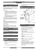
OV500 SERIES RACK OVEN - GENERAL GENERAL composite bearings on power rack lift shaft - no lubrication required. INTRODUCTION General CONTROL LOCATION OV500G1 & OV500E1 rack ovens hold one single rack and OV500G2 & OV500E2 rack ovens hold two single racks or one double rack. Oven features: • Powered rack lift with high temperature bearings and a clutch rotating system designed to stop the rack in the event of a jam without damage to the rotation motor or losing rack alignment.
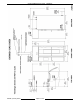
OV500 SERIES RACK OVEN - GENERAL OV500G1 GAS OVEN SPECIFICATIONS â WATER: 1/2" NPT, 30-75 PSI cold water required, customer to install in-line filter, shut off valve and line strainer. Ï DRAIN: 6 1/4" (front) or 7" (rear) connection A.F.F. (See notes). Route to air-gap drain. Do not slope drain upwards. Plug the drain connection that is not in use. Rear Drain: 1/2" NPTF Front Drain: 1/2" NPTF Ð POWER: Two supplies required.
OV500 SERIES RACK OVEN - GENERAL F25361 (January 2010) Page 6 of 60
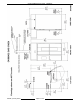
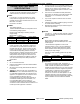
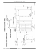
OV500 SERIES RACK OVEN - GENERAL OV500G2 GAS OVEN SPECIFICATIONS 7. â WATER: 1/2" NPT, 30-75 PSI cold water required, customer to install in-line filter, shut off valve and line strainer. Ï DRAIN: 2 3/4" (front) or 5 1/2" (rear) connection A.F.F. (See notes). Route to air-gap drain. Do not slope drain upwards. Plug the drain connection that is not in use. Kit provided to extend drain to either side of oven. Rear Drain: 3/4" NPTF Front Drain: 3/8" NPTF Ð POWER: Two supplies required.
OV500 SERIES RACK OVEN - GENERAL F25361 (January 2010) Page 8 of 60
OV500 SERIES RACK OVEN - GENERAL OV500E1 ELECTRIC OVEN SPECIFICATIONS 5. The floor must be of non-combustible material, and must be level with surrounding area with a maximum slope of 1/8" per foot up to 3/4" maximum in all directions. Floor anchors require a minimum 1" thick solid floor substrate. 6. Oven is UL/C-UL classified and CSA (AGA/CGA) approved for 0" clearance on the side and rear walls. Unit requires 1" to 4" clearance for rear drain connection. 7.
OV500 SERIES RACK OVEN - GENERAL F25361 (January 2010) Page 10 of 60
OV500 SERIES RACK OVEN - GENERAL 5. OV500E2 ELECTRIC OVEN SPECIFICATIONS â WATER: 1/2" NPT, 30-75 PSI cold water required, customer to install in-line filter, shut off valve and line strainer. Ï DRAIN: 2 3/4" (front) or 5 1/2" (rear) connection A.F.F. (See notes). Route to air-gap drain. Do not slope drain upwards. Plug the drain connection that is not in use. Kit provided to extend drain to either side of oven. Rear Drain: 3/4" NPTF Front Drain: 3/8" NPTF Ð ELECTRICAL: Two supplies required.
OV500 SERIES RACK OVEN - GENERAL F25361 (January 2010) Page 12 of 60
OV500 SERIES RACK OVEN - REMOVAL AND REPLACEMENT OF PARTS REMOVAL AND REPLACEMENT OF PARTS STEAM PANEL NOTE: Hand tighten only, do not use power tools when installing panel screws. 1. Remove screws securing steam panel to baking compartment rear wall (through access holes). 4. Reverse the procedure to install. RACK ROTATOR ASSEMBLY Removal 1. 2. 3. Remove screws securing steam panel to left baking compartment wall. Remove rack carrier. A. Support rack carrier. B. Loosen set screws. C.
OV500 SERIES RACK OVEN - REMOVAL AND REPLACEMENT OF PARTS 5. Lift rack rotator assembly, which will include the rack lift shaft, from rack lift assembly. NOTE: Removal of actuator housing bolt may be necessary for rack rotator assembly removal. lift arm only if replacing. Assembly 1. Install female half of spherical bearing into the lift arm if removed. 2. Apply high temperature grease to female half of spherical bearing. Spread grease evenly across bearing surface. 3.
OV500 SERIES RACK OVEN - REMOVAL AND REPLACEMENT OF PARTS 8. SERVICE PROCEDURES AND ADJUSTMENTS. Install clutch disk. 19. Check for proper operation. ROTATOR MOTOR Removal 9. 1. Block the rack rotator assembly in a position to access the motor mounting bolts and sprocket set screw. 2. Disconnect the rotator motor lead wires. 3. Remove cooling fan from motor. 4. Loosen rotator motor sprocket set screw. 5. Remove rotator motor mounting screws. 6.
OV500 SERIES RACK OVEN - REMOVAL AND REPLACEMENT OF PARTS Assembly 1. Install rotator motor shaft through rotator assembly and rotator sprocket. 2. Position sprocket onto rotator motor shaft, collar side towards motor. 3. Install rotator motor mounting screws and align sprocket and rotator drive chain. Ensure rotator drive chain is not in a bind. 4. Secure set screw onto motor shaft. 5. Connect rotator motor lead wires. NOTE: Shaft rotation viewed from top of oven.
OV500 SERIES RACK OVEN - REMOVAL AND REPLACEMENT OF PARTS 8. Install lower actuator arm pin through lift pin. 9. Position the rack rotator assembly so the top actuator mounting brackets will align with the rotator assembly. 1. If necessary, move the gas line out of the way. 2. Shut off water supply line and remove exterior water supply that is within the boundary of blower cover. 3. Disconnect lead wires at motor junction box. 4. Remove motor junction box. 5.
OV500 SERIES RACK OVEN - REMOVAL AND REPLACEMENT OF PARTS 14. Remove heat slinger and mounting bracket from motor. 15. Reverse the procedure to install. 4. Reverse procedure to install. 5. Check GAS PRESSURE as outlined under SERVICE PROCEDURES AND ADJUSTMENTS. 6. Operate oven and check for proper operation. GAS VALVE GAS MANIFOLD / ORIFICES A. CHECK ALL JOINTS PRIOR TO THE GAS VALVE (SOLENOID) BEFORE LIGHTING UNIT. B. CHECK ALL JOINTS AFTER TO THE GAS VALVE (SOLENOID) AFTER THE UNIT IS LIT.
OV500 SERIES RACK OVEN - REMOVAL AND REPLACEMENT OF PARTS 4. 5. Remove screws securing burner cover to oven. A. CHECK ALL JOINTS PRIOR TO THE GAS VALVE (SOLENOID) BEFORE LIGHTING UNIT. B. CHECK ALL JOINTS AFTER TO THE GAS VALVE (SOLENOID) AFTER THE UNIT IS LIT. 1. Open control compartment door to gain access to burner assembly. 2. Remove screws securing burner cover to oven. 3. Disconnect gas manifold at the union fitting OV500G1 & OV500G2. 4.
OV500 SERIES RACK OVEN - REMOVAL AND REPLACEMENT OF PARTS 5. Remove screw securing hot surface ignitor to burner side rack assembly, and pull ignitor out. 9. Remove steam and exchanger compartment panels. 6. Remove screws securing burner rack enclosure from oven. 10. Remove steam ball assemblies. 11. Access draft inducer box on top of oven and remove. Disconnect deflector baffle from hangers above heat exchanger tubes and remove from top of tubes OV500G1 & OV500G2. 12.
OV500 SERIES RACK OVEN - REMOVAL AND REPLACEMENT OF PARTS IGNITION MODULE 1. Open the control compartment door to gain access to ignition module. 2. Remove control box cover. 3. Disconnect lead wires from the ignition module. Note Wire locations or refer to wiring diagram. 4. Remove screws securing ignition module to oven. 5. Reverse the procedure to install. 14. OV500G1 & OV500G2 oven pull rear of heat exchanger into the oven cavity.
OV500 SERIES RACK OVEN - REMOVAL AND REPLACEMENT OF PARTS 2. Remove controller rear cover. NOTE: When installing ensure stand off spacers are installed behind controller board. 5. Reverse the procedure to install. 6. Verify controller default settings. 7. Check oven for proper operation. HIGH LIMIT SWITCH NOTE: On OV500G1 & OV500G2 oven, access high limit switch at top of oven in service entrance box. On OV500E1 & OV500E2 oven, access high limit switch at the bottom of the control component box. 1.
OV500 SERIES RACK OVEN - REMOVAL AND REPLACEMENT OF PARTS DRAFT INDUCER MOTOR To install: 1. Install high limit in component box or service entrance box. 2. Connect lead wires to high limit. 3. Route high limit capillary tube to top of oven. 4. Mark 12" from end of probe. 5. Insert male compression fitting onto high limit probe. 6. Install female fitting into center probe location. 7. Insert 12" of high limit probe into oven.
OV500 SERIES RACK OVEN - REMOVAL AND REPLACEMENT OF PARTS 12. Check for proper operation. PRESSURE SWITCHES NOTE: Make note of dimension that draft inducer fan blade is located on motor shaft, for installing fan blade on to new motor. 7. 1. Open control compartment door to gain access to draft inducer vacuum switch and hood vent pressure switch. 2. Disconnect lead wires from appropriate pressure switch. 3. Remove tube from pressure switch. 4. Remove screws securing pressure switch. 5.
OV500 SERIES RACK OVEN - REMOVAL AND REPLACEMENT OF PARTS OVEN CAVITY VENT SWITCH 3. Disconnect lead wires from vent motor and vent switch. 4. Loosen vent cam set screw and remove cam from shaft. NOTE: Mark location of cam on vent motor shaft. 1. Remove screws securing vent motor cover from vent motor box. 2. Disconnect lead wires from vent switch. 3. Remove screws securing vent switch from vent bracket. 4. Reverse procedure to install.
OV500 SERIES RACK OVEN - REMOVAL AND REPLACEMENT OF PARTS 11. Tighten male compression fitting against second set of spacers to secure backup thermostat bulb. 12. Install probe cover. 6. Access the thermostat bulb at top of the oven. 7. Remove screws securing probe cover from oven. 8. Remove compression fitting and remove thermostat bulb. 13. Check oven for proper operation. TEMPERATURE PROBE 1. Access the probe at top of the oven. 2. Remove screws securing probe cover from oven. 3.
OV500 SERIES RACK OVEN - REMOVAL AND REPLACEMENT OF PARTS EPROM REPLACEMENT 1. Open the control compartment door to gain access to controller. 2. Remove the controller box cover. Static electricity will damage the controller board. Use an anti-static grounding kit when servicing the controller. 3. Remove the prom from the controller. 4. Install the new prom. Verify orientation notch and carefully align pins of prom. B.
OV500 SERIES RACK OVEN - SERVICE PROCEDURES AND ADJUSTMENTS A. Remove screws on opposite side of door jamb and install door strike. 6. B. Install screws onto other side of door jamb catch was removed from. C. Install both door catches to opposite door jamb. Remove door catches from door jamb. 7. Adjust the DOOR as outlined under SERVICE PROCEDURE AND ADJUSTMENTS. 8. Install door sweep onto door assembly at bottom of door.
OV500 SERIES RACK OVEN - SERVICE PROCEDURES AND ADJUSTMENTS IGNITION MODULE SELF DIAGNOSTICS CONTROLLER TEMPERATURE CALIBRATION Ignition module makes three attempts to light burner before proceeding to lock-out mode. Certain components in this system are subject to damage by electrostatic discharge during field repairs. A field service grounding kit is available to prevent damage. The field service grounding kit must be used anytime the control board is handled. 1.
OV500 SERIES RACK OVEN - SERVICE PROCEDURES AND ADJUSTMENTS A. After the desired time is set and the seconds. Up/Down Arrows have not been pressed 3. Press Set Temp Up Arrow to select set-up for 5 seconds, the colon will start to flash item shown in set temp display. indicating the clock has continued running. 4. Use the Bake Timer Arrows to adjust set-up PARAMETER SETTINGS values in the bake timer display. 1. 2. Press the Power On/Off keypad to turn the oven off.
OV500 SERIES RACK OVEN - SERVICE PROCEDURES AND ADJUSTMENTS P19 Lights mode 0= auto operation 1= continuously ON P20 Restricted operator mode 0= Standard 1= Restricted Operation Mode P21 Advanced Energy Saving Mode 0= Standard 1= Advanced Energy Saving Mode P22 OV210 Mode 0= Standard 1= OV210 Mode P23-P24 Unused P25 Communicate Mode 0= Direct Connect 1= NAFEM Protocol Select 1 for lights on continuously (when oven is on) or select 0 for automatic operation, lights will turn off automatically aft
OV500 SERIES RACK OVEN - SERVICE PROCEDURES AND ADJUSTMENTS indicator light is illuminated. OVEN TEMPERATURE SAFETY ALARM NOTE: Standard feature, no parameter setup required. H. Consult with Bakery Manager for required start and end of bake time. If the temperature at the oven probe is between 570 to 600°F. (299 to 316EC.) for ten seconds, the controller will do the following: I.
A. OV500 SERIES RACK OVEN - SERVICE PROCEDURES AND ADJUSTMENTS controller will enter Kosher Active Mode, and If time is remaining on timer counting have the following operating characteristics: down, oven will not shut down. B. Once timer shows 0:00 the oven will shut down in 15 minutes, P17. A. The minimum set temperature is 200°F. (93°C.). C. Operator can start oven while in Auto off Time by pressing the On/Off keypad, set timer to a minimum of 30 minutes and press start keypad. B.
4. OV500 SERIES RACK OVEN - SERVICE PROCEDURES AND ADJUSTMENTS 1. Attach a manometer to 1/8" NPT inlet pressure To disable Kosher Operation Mode - Bakery tap on gas valve. Mode: A. Oven controller off. B. Press and hold the Airflow Delay Arrow keypad while pressing the Power On/Off keypad for 3 seconds. C. Press the Bake Timer Arrows until Bake Timer Display reads 0. D. Press the Power On/Off keypad, oven in Bakery Mode (standard operation). BURNER ADJUSTMENTS 2.
7. OV500 SERIES RACK OVEN - SERVICE PROCEDURES AND ADJUSTMENTS With a burner flame established and all other gas equipment on the supply line lite, adjust the manifold pressure as indicated in the following charts or as indicated on the oven data plate. NOTE: Accurate gas pressure adjustment can only be made with the burner on. NOTE: Turn adjustment screw Clockwise to increase the pressure, Counterclockwise to decrease pressure. BTU/HR W.C. kCAL/HR cm W.C. Mj/HR kPa W.C. kCAL/HR cm W.C.
OV500 SERIES RACK OVEN - SERVICE PROCEDURES AND ADJUSTMENTS NOTE: The following chart is for reference only. If the manifold pressure must be adjusted to accommodate the altitude you must contact Bakery Product Support for a corrected data plate and orifice part number. ALTITUDE CORRECTION CHART ELEVATION IN FT. OV500G1 OV500G1 OV500G2 OV500G2 Natural Gas Propane Gas Natural Gas Propane Gas Orifice #53 Orifice #63 Orifice #49 Orifice #56 Orifice Dia. 0.0595 Orifice Dia. 0.037 Orifice Dia.
8. OV500 SERIES RACK OVEN - SERVICE PROCEDURES AND ADJUSTMENTS If manifold pressure was unattainable, light burner and all other gas equipment on the supply line and check gas supply line flow pressure. If gas supply line flow pressure not attainable find the source of the problem. OV500G1 GAS SUPPLY LINE FLOW PRESSURE NATURAL GAS PROPANE GAS BTU/HR 180,000 180,000 W.C. 5.0" - 14.0" 12.0" - 14.0" kCAL/HR 45,400 45,400 cm W.C. 12.7 - 25.4 30.5 - 35.6 Mj/HR 190 190 kPa 1.25 - 2.50 3.00 - 3.
OV500 SERIES RACK OVEN - SERVICE PROCEDURES AND ADJUSTMENTS NOTE: If reading is below 0 microamps reverse FLAME SENSE LOCATION meter leads and take another reading. 1. Flame sensor is located at the bottom of the burner assembly. 2. Flame sensor is positioned at the lower edge of the last end shot burner. 1. Verify the manifold pressure as outlined under BURNER ADJUSTMENTS. 3. Flame sensor should be parallel to the face of the burner and horizontal to the lower edge. 2.
OV500 SERIES RACK OVEN - SERVICE PROCEDURES AND ADJUSTMENTS SINGLE POINT VENTING DRAFT INDUCER TEST 3. 1. Access the component panel area for single point venting and for dual point venting access draft diverter above oven. 2. Single point venting connect incline manometer or equivalent to draft inducer tubing. For dual point venting insert incline manometer tube 6" above draft diverter. Set oven temperature to 450EF (230°C.
3. OV500 SERIES RACK OVEN - SERVICE PROCEDURES AND ADJUSTMENTS There should be a vacuum reading of: OV500G1 Oven Temp Cold 400°F. 204.4°C. Natural Gas (minimum readings) -0.46 "W.C. -11.7 mm W.C. -0.11 kPa -0.32 "W.C. -8.13 mm W.C. -0.08 kPa Propane (minimum readings) -0.46 "W.C. -11.7 mm W.C. -0.11 kPa -0.32 "W.C. -8.13 mm W.C. -0.08 kPa OV500G2 Oven Temp Cold 400°F. 204.4°C. Natural Gas 300k Btu/h 350k Btu/h 75,600 kCAL/HR 88,200 kCAL/HR 317 Mj/HR 370 Mj/HR Min. -0.43 "W.C. Min. -0.36 "W.C. -10.
D. OV500 SERIES RACK OVEN - SERVICE PROCEDURES AND ADJUSTMENTS If back draft indicated (smoke not going up draft diverter relief opening) the oven must not be operated, until proper adjustments have been made (correct flue stack to have adequate up draft through the draft diverter relief opening). DOOR ADJUSTMENT Check 1. With the door closed, visually check gap around door jamb and edge of door, gap should be equal on both sides. 2. Loosen mounting screws and adust latches towards door gasket.
2. OV500 SERIES RACK OVEN - SERVICE PROCEDURES AND ADJUSTMENTS Access door switch in control compartment. 3. With oven door closed, door switch actuator guide should operate actuator plate inside control compartment and door switch. 4. Loosen the door switch screws and move the door switch until door switch is operated. 5. Tighten door switch screws. 5. Tighten screws. 6. Check for proper operation. RACK POSITION ADJUSTMENT 1.
OV500 SERIES RACK OVEN - SERVICE PROCEDURES AND ADJUSTMENTS NOTE: Do not bend actuator for rack height adjustment. 4. Tighten the lift switches bracket screws. 5. Check for proper operation. Adjustment for "C" Channel Type Rack NOTE: Locate customer
A. B. OV500 SERIES RACK OVEN - SERVICE PROCEDURES AND ADJUSTMENTS Verify that rack(s) wheels (when at the rear location of the baking compartment) do not drag on the oven floor. If wheels drag, move upper lift switch to the upper holes in upper & lower lift switch bracket. 2) B. C. Test with oven at desired operating temperature for 15 minutes. D. If wheels drag, then oven floor or racks do not meet manufactured specifications. Install actuator housing cover.
OV500 SERIES RACK OVEN - SERVICE PROCEDURES AND ADJUSTMENTS AIR AND ANGLE SHUTTER ADJUSTMENTS FACTORY SETTING ON COSTCO OVENS ONLY FACTORY SETTINGS STANDARD DOUBLE OVENS Page 45 of 60 F25361 (January 2010)
OV500 SERIES RACK OVEN - SERVICE PROCEDURES AND ADJUSTMENTS FACTORY SETTINGS ON PANERA BREAD OVENS ONLY FACTORY SETTINGS ON COSTCO OVENS ONLY General Information NOTE: Before making any shutter adjustments, refer to the bakery installation basics procedure. 1. Factory settings are used for a starting point on a new oven. Once an oven has been started up and has baked satisfactorily, there is no need to return to factory settings. 2.
3. OV500 SERIES RACK OVEN - ELECTRICAL OPERATION The shutters are the short L shaped panels of stainless steel located on the right rear corner panel of the bake chamber. There are 12 shutters per oven, consisting of 24 adjustable air volume settings and 12 adjustable angle settings. 4. Air volume adjustments modifies the heat from top to bottom of rack(s). 5. Shutter angle adjustments direct the heat to side or center of individual pans on a rack. 6. Oven pressure panel feeler gauge Part No.
OV500 SERIES RACK OVEN - ELECTRICAL OPERATION Ignition Control Module . . . . . Controls and monitors gas heating. Energizes gas valve coil, hot surface ignitor, draft inducer, and monitors presence of flame. Hot Surface Ignitor . . . . . . . . . When energized, ignites gas. Roll Out Switch . . . . . . . . . . . . Opens if flame goes beyond confined area of heat exchanger and into control compartment. At 350EF. (177EC.) opens circuit to ignition module (manual reset). Flame Sensor . . . . . . . . . . . . .
OV500 SERIES RACK OVEN - ELECTRICAL OPERATION A. 24V transformer heating circuit / 24V C. CR4 coil energized. transformer door switch circuit / control 1) CR3 de-energized. board / M3 / CR1 / Lights / MR1 / SV1 / M2 2) Circuit path to lift motor completed thru / M4 / M5 / CR3 / CR2 back up control only CR4 N.O. / circuit breakers. 9. D. Circulation motor energized. High limit, roll out switch and overloads OL1and OL2 closed. E. Refer to burner sequence of operation. Pre - Heat Cycle 5.
OV500 SERIES RACK OVEN - ELECTRICAL OPERATION 1) CR4 de-energized. BURNER SEQUENCE OF OPERATION 2) Door input removed from control board (A2 not lit). 3) Circuit to rotator motor continues thru CR4 N.C. 1. Power (24VAC) to ignition module L1 and R (A4 lit). D. Rack continues to rotate until rack pointer operates rack position switch #1 and #2. (Rack centered in door). 2. 24VAC output from control (A8 lit) to ignition module terminal W and one side of the draft inducer pressure switch. A.
OV500 SERIES RACK OVEN - ELECTRICAL OPERATION COMPONENT LOCATION OV500G1 & OV500G2 COMPONENT LOCATION OV500E1 & OV500E2 COMPONENT LOCATION Page 51 of 60 F25361 (January 2010)
OV500 SERIES RACK OVEN - ELECTRICAL OPERATION WIRING DIAGRAMS SCHEMATIC - WITH BACKUP CONTROLS HOBART BAKERY SYSTEMS DERIVED FROM DRAWING NO. 01-10I663 REV.
OV500 SERIES RACK OVEN - ELECTRICAL OPERATION HOBART BAKERY SYSTEMS DERIVED FROM DRAWING NO. 01-10I664 REV.
OV500 SERIES RACK OVEN - ELECTRICAL OPERATION HEATING CIRCUIT - BURNER HOBART BAKERY SYSTEMS DERIVED FROM DRAWING NO. 01-10I665 REV.
OV500 SERIES RACK OVEN - TROUBLESHOOTING OVEN TROUBLESHOOTING SYMPTOM Oven completely inoperative. No display on control. Oven does not operate. Display lit or display flashing and oven cavity lights on. Oven does not operate. Display shows Shdn (shutdown) in the bake timer display and flashes the Oven Temp display while alarm sounds. Oven does not operate. Erratic display. 1. 2. 3. 4. 1. 2. 3. 4. 1. 1. 2. Rack does not lift when bake cycle is initiated. 1. 2. 3. 4. 5.
OV500 SERIES RACK OVEN - TROUBLESHOOTING SYMPTOM Rack does not lower when rack stops in load/unload position when door is opened during or at end of bake cycle. 1. 2. 3. 4. 5. Rack stops in wrong position or doesn't stop after 1. door is opened. 2. 3. 4. 5. No steam or low volume of steam. 1. 2. 3. 4. 5. Excessive moisture in oven. 1. 2. 3. 4. Recovery time slow after steaming. 1. 2. 3. 4. 5. Incorrect heat. 1. 2. 3. 4. 5. Burner does not light. 1. 2. 3. High or low draft pressure in oven draft inducer. 1.
OV500 SERIES RACK OVEN - TROUBLESHOOTING IGNITION MODULE TROUBLESHOOTING SYMPTOM Diagnostic LED continuous ON - Ignition control powered, but module does not have outputs at appropriate times. 1. No draft inducer output. 2. No gas valve output. 3. No ignitor output. Diagnostic LED '1' flash - Airflow fault. Module doesn't have draft inducer pressure switch input. Diagnostic LED '2' flashes - Flame no call for heat. NOTE: Flame continues after controller set temperature is satisfied.
OV500 SERIES RACK OVEN - TROUBLESHOOTING BURNER TROUBLESHOOTING F25361 (January 2010) Page 58 of 60
OV500 SERIES RACK OVEN - NOTES - Page 59 of 60 F25361 (January 2010)
OV500 SERIES RACK OVEN - NOTES - F25361 (January 2010) Printed in U.S.A.