705 TENDERIZER TECHNICAL MANUAL SERIAL NUMBERS STARTING WITH 31 OR 9234-11121 SPECIFICATION SHEET INSTALLATION INSTRUCTIONS OPERATION INSTRUCTIONS CLEANING INSTRUCTIONS MAINTENANCE INSTRUCTIONS TROUBLE SHOOTING INSTRUCTIONS WIRING DIAGRAMS CATALOG OF REPLACEMENT PARTS RECOMMENDED SPARE PARTS LIST
Need other Hobart Services? • Warranty Registration • Delivery and Installation • Preventive Maintenance • Hobart Service Contracts • Extended Warranty Contracts • Parts and Accessories • Specialty Programs • Water Treatment Programs 705 Tenderizer Technical Manuals Page 2 of 34
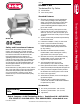
Item # Model 705 Tenderizer/Stir Fry Cutter ❏ 705 Tenderizer ❏ 705-S Stir Fry Cutter Standard Features ❑ Model 705 Tenderizer consists of 86 blades on two rollers providing 1,118 cutting edges; design cuts and knits the meat from both sides simultaneously for smooth meat flow and a uniform tenderizing pattern that tightly seals in juices when cooked ➤ ❑ Model 705-S Stir Fry Cutter produces clean, uniform strips of meat to a pre-set thickness of either 1/2” (13 mm) or 3/8” (10 mm) thick; up to 14 stainles
Model 705 Tenderizer/Stir Fry Cutter Model No. 705 Motor Tenderizer/Stir Fry Cutter Model 705 1-speed 1/2 HP Product Capacity 705-S Slice Thickness Output Speed Product Dimensions Width A Depth B Height C 1-1/4” (32 mm) thick 7-7/8” (200 mm) wide 1/2”, 3/8” (13, 10 mm) 120 RPM 16-1/8” (410 mm) 16-1/4” (413 mm) Electrical 115/60/1 Weight Net 62 lbs. (28 kg) Ship 70 lbs.
OWNER/OPERATOR MANUAL MODELS 705 & 705S TENDERIZER NOTICIA IMPORTANTE Este manual contiene importantes instrucciones de seguridad que deben ser seguidas el pie de la letra cuando utilice esta maquina. IMPORTANT NOTICE This manual contains Important Safety Instructions which must be strictly followed when using this equipment.
BEFORE USING THIS EQUIPMENT Berkel’s tenderizers are designed to tenderize/slice meat and other food products safely and efficiently. However, unless the operator is properly trained and supervised, there is the possibility of a serious injury. It is the responsibility of the owner to ensure that this tenderizer is used properly and safely, strictly following the instructions contained in this manual and any requirements of local law.
TABLE OF CONTENTS Page General Safety Instructions .................................................................................................................. 2-3 Equipment Identification ..................................................................................................................... 4 Intended Uses ...................................................................................................................................... 5 Safety Characteristics ......................
PELIGRO CUCHILLA FILOSA para evitar serios accidentes a su persona siga las instrucciones de este manual y 1. NUNCA utlice esta mçquina sin previa instrucciùn y autorizaciùn de su supervisor. 2. LA MáQUINA DEBE apoyarse sobre un nivel solido y plano. 3. LOS PROTECTORES deben colocarse ANTES de enchufar y operar la máquina. 4. SIEMPRE utilice el enchufe original proveido por el fabricante. 5. SIEMPRE utilice el utensillo para empujar la comida - nunca su mano. 6. NUNCA TOQUE LA CUCHILLA CON LA MANO.
WARNING SHARP KNIFE BLADE to avoid serious personal injury follow all the instructions in this manual and 1. NEVER touch this machine without training and authorization by your supervisor. 2. MACHINE MUST BE on solid level support. 3. GUARDS MUST BE in place before plugging in and turning on machine. 4. ALWAYS use three pronged plug provided. 5. ALWAYS use food pusher not your hand. 6. NEVER TOUCH ROTATING KNIFE. 7. KEEP hands, arms, hair and loose clothing clear of all moving parts. 8.
EQUIPMENT IDENTIFICATION Safety Cover Clutch Gear Blade and Frame Assembly Locking Lever ON/OFF Switch 4 • 705 & 705S OWNER/OPERATOR MANUAL 705 Tenderizer Technical Manuals Page 10 of 34
INTENDED USES The 705 and 705S tenderizers are designed for processing the following types of food products: • • • • Beef Poultry Pork Vegetables The following items are not suitable to be processed on the 705 and 705S tenderizers: • • • Products on/with bones Frozen products Non-food products SAFETY CHARACTERISTICS • • • The cover is equipped with a safety interlock that will not allow the tenderizer to be turned on unless the cover is in the down position.
34567890123456789012345678901212345678901234567890123456789012123456789012345678901234567890121234567890123456789012345678901212345678901234567 1234567890123456789012345678901212345678901234567890123456789012123456789012345678901234567890121234567890123456789012345678901212345678901234567 1234567890123456789012345678901212345678901234567890123456789012123456789012345678901234567890121234567890123456789012345678901212345678901234567 12345678901234567890123456789012123456789012345678901234567890121234567890
9. All removable parts can be soaked and scrubbed using a bristled brush and good quality detergent approved for food processing equipment. 10. Rinse thoroughly and set aside to air dry while you are washing the machine case. 11. Sanitize all blade and frame assembly parts and tenderizer unit. REASSEMBLY 1. Replace stripper plates with solid flanges to the outside of the assembly, teeth to the center and pointing up. (Front and back stripper plates for the tenderizer group are interchangeable.) 2.
MODELS Model 705: Model 705S: Model SFC: Tenderizer (includes tenderizer blade and frame assembly). Stir-Fry Cutter (includes stir-fry cutter blade and frame assembly). Stir-Fry Blade and Frame Assembly (to convert 705 and earlier model Berkel to optional stir-fry cutter use). TROUBLESHOOTING Should your tenderizer fail to function properly, here are a few things you can check before calling a Designated Berkel Service Location for service. Product not tenderizing or slicing properly: 1.
REPAIR PARTS/REPAIR SERVICE Please contact your Designated Berkel Service Location for any repair parts and/or repair service required on your Berkel tenderizer. Additional information may be obtained from: Service Support Center Berkel Company 4406 Technology Drive South Bend, Indiana 46628-9700 574/232-8222 · Fax 574/232-8116 (800) 348-0251 SPECIFICATIONS Motor: 1/2hp, 115 volt, 60 cycle single phase, 7.
WARRANTY Berkel Company (“Berkel”) warrants to the Buyer of new equipment that said equipment, when installed in accordance with our instructions and subjected to normal use, is free from defects in material or workmanship for a period of one (1) year from the date of sale.1 BERKEL SPECIFICALLY DISCLAIMS ANY IMPLIED WARRANTY OF MERCHANTABILITY OR EXPRESS OR IMPLIED WARRANTY OF FITNESS FOR A PARTICULAR PURPOSE.
705 Tenderizer Technical Manuals Page 17 of 34 DERIVED FROM 01-409234-11121 705 TENDERIZER ELECTRICAL WIRING DIAGRAM WITH SERIAL NO.
CATALOG OF REPLACEMENT PARTS MODEL 705 & 705S TENDERIZER EFFECTIVE APRIL 2010 705 Tenderizer Technical Manuals Page 18 of 34
MODEL 705 & 705S TENDERIZER REPLACEMENT PARTS Table of Contents 3 5 7 9 11 13 15 F-43215 (April 2010) ELECTRICAL UNIT HOUSING UNIT GEARBOX AND MOTOR ASSEMBLY BLADE FRAME ASSEMBLY STIR FRY TRACTION SHAFT ASSEMBLY STIR FRY KNIFE SHAFT ASSEMBLY TENDERIZER BLADE AND SHAFT ASSEMBLY -2- 705 Tenderizer Technical Manuals Page 19 of 34
MODEL 705 & 705S TENDERIZER REPLACEMENT PARTS 14 15 13 12 17 16 11 10 18 9 8 19 1 3 4 5 7 2 6 PL-59355 ELECTRICAL UNIT ILLUS. PL-59355 1 2 3 4 5 6 7 8 9 10 11 12 13 14 15 16 17 18 19 PART NO.
MODEL 705 & 705S TENDERIZER REPLACEMENT PARTS 6 2 3 1 4 5 7 16 8 9 10 15 14 11 13 12 HOUSING UNIT F-43215 (April 2010) -4- 705 Tenderizer Technical Manuals Page 21 of 34 PL-59354
MODEL 705 & 705S TENDERIZER REPLACEMENT PARTS HOUSING UNIT ILLUS. PL-59354 1 2 3 4 5 6 7 8 9 10 11 12 13 14 15 16 PART NO. 01-409234-00020 01-403375-00157 01-403275-00012 01-403375-00156 01-402775-00001 01-403775-00275 01-402175-01864 01-404575-00801 01-402175-03769 01-402275-00070 01-403875-00053 01-403375-00664 01-403675-00051 01-403375-00191 01-403775-00279 01-403175-00152 01-404975-00108 NAME OF PART AMT. Cover – Tenderizer Assy. (Incls. Items 2 thru 5) ............................................
MODEL 705 & 705S TENDERIZER REPLACEMENT PARTS 1 2 3 4-5 20-21 17 19 18 6 16 7 15 14 9 8 13 12 10-11 CURRENT CONSTRUCTION (Units With Serial Numbers 9234-11121-OR 31-XXX-XXXX) 22 23 24 PREVIOUS CONSTRUCTION (Units With Serial Numbers 9234-01121-XXX) PL-59357 GEARBOX AND MOTOR ASSEMBLY F-43215 (April 2010) -6- 705 Tenderizer Technical Manuals Page 23 of 34
MODEL 705 & 705S TENDERIZER REPLACEMENT PARTS GEARBOX AND MOTOR ASSEMBLY ILLUS. PL-59357 PART NO.
MODEL 705 & 705S TENDERIZER REPLACEMENT PARTS 3-4 5 6 2 1 8-9 10 7 18 11 12 13 14 16-17 19-20 PL-59356 15 BLADE FRAME ASSEMBLY F-43215 (April 2010) -8- 705 Tenderizer Technical Manuals Page 25 of 34
MODEL 705 & 705S TENDERIZER REPLACEMENT PARTS BLADE FRAME ASSEMBLY ILLUS. PL-59356 1 2 3 4 5 6 7 8 9 10 11 12 13 14 15 16 17 18 19 20 PART NO.
MODEL 705 & 705S TENDERIZER REPLACEMENT PARTS 2-3 1 4 THRU 7 8 9 10 11 12-13-14 15 PL-59360 STIR FRY TRACTION SHAFT ASSEMBLY F-43215 (April 2010) - 10 - 705 Tenderizer Technical Manuals Page 27 of 34
MODEL 705 & 705S TENDERIZER REPLACEMENT PARTS STIR FRY TRACTION SHAFT ASSEMBLY ILLUS. PL-59360 1 2 3 4 5 6 7 8 9 10 11 12 13 14 15 PART NO. 01-404575-00061 01-403375-01019 01-403375-01018 01-403375-01045 01-403375-01048 01-403375-01049 01-403375-01017 01-403475-00698 01-403475-00699 01-403475-00698 01-403475-00050 01-403375-01017 01-403475-00699 01-403375-01018 01-404675-00106 01-404675-00778 01-404675-00780 01-404675-00782 01-404675-00757 NAME OF PART AMT. Shaft – Blade (Rear) .......................
MODEL 705 & 705S TENDERIZER REPLACEMENT PARTS 1 2 3 THRU 6 7 8 9-10-11 12 PL-59359 STIR FRY KNIFE SHAFT ASSEMBLY F-43215 (April 2010) - 12 - 705 Tenderizer Technical Manuals Page 29 of 34
MODEL 705 & 705S TENDERIZER REPLACEMENT PARTS STIR FRY KNIFE SHAFT ASSEMBLY ILLUS. PL-59359 1 2 3 4 5 6 7 8 9 10 11 12 PART NO. 01-404575-00059 01-403375-01020 01-403375-01047 01-403375-01050 01-403375-01051 01-403375-01021 01-403475-00050 01-403475-00697 01-403375-01020 01-403475-00699 01-403375-01019 01-404675-00104 01-404675-00777 01-404675-00779 01-404675-00781 01-404675-00756 NAME OF PART AMT. Shaft – Blade ..........................................................................................
MODEL 705 & 705S TENDERIZER REPLACEMENT PARTS 1-2 3 4 5 6 7 8 9-10 PL-59358 TENDERIZER BLADE AND SHAFT ASSEMBLY F-43215 (April 2010) - 14 - 705 Tenderizer Technical Manuals Page 31 of 34
MODEL 705 & 705S TENDERIZER REPLACEMENT PARTS TENDERIZER BLADE AND SHAFT ASSEMBLY ILLUS. PL-59358 1 2 3 4 5 6 7 8 9 10 PART NO. 01-404575-00059 01-404575-00061 01-403275-00014 01-403375-00165 01-403275-00014 01-403475-00050 01-403375-00164 01-403275-00014 01-404675-00104 01-404675-00106 01-404675-00107 01-404675-00105 NAME OF PART AMT. Shaft – Blade (Front) ................................................................................................................. 1 Shaft – Blade (Rear) .........
MODEL 705 & 705S TENDERIZER REPLACEMENT PARTS FORM 43215 APRIL 2010 705 Tenderizer Technical Manuals Page 33 of 34 PRINTED IN U.S.A.
705 TENDERIZER March 2010 PRODUCT SERVICE DEPARTMENT TROY, OH. 45374-0001 RECOMMENDED SPARE PARTS LIST 705 TENDERIZER Serial Numbers Starting 31 or 9234-11121 Qty Part Number Description 1 01-404175-00722 Motor 115V/60/1 1 01-402375-00134 Coupling, New Style 1 01-402675-00015 Switch, Rocker 1 01-403675-00050 Switch Boot 1 01-404175-00020 Switch, Micro 1 01-404675-00104 Bearing Assy., with Screw 1 01-404675-00106 Bearing Assy.