I N S T R U C T MODEL FP400 FOOD PROCESSOR I O N S ML-104751 701 S. RIDGE AVENUE TROY, OHIO 45374-0001 FORM 33966 Rev.
TABLE OF CONTENTS MODEL FP400 FOOD PROCESSOR ............................................................................................. 3 GENERAL.......................................................................................................................................... 4 INSTALLATION ................................................................................................................................. 4 Unpacking ..................................................................
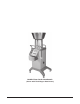
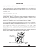
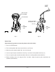
MODEL FP400 FOOD PROCESSOR (Shown with Feed Hopper Attachment) © HOBART CORPORATION, 1998 –3–
Installation, Operation and Care of HOBART MODEL FP400 FOOD PROCESSOR PLEASE KEEP THIS MANUAL FOR FUTURE USE GENERAL The FP400 Food Processor is used for slicing, shredding, grating, Julienne cutting and dicing vegetables, fruits, or cheese. A wall rack, and a wide range of slicer, shredder, and dicing plates are available accessories. The machine is built for 208-240 volt, 60 Hertz, 3 phase electrical supply.
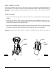
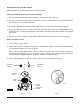
VERIFY CORRECT ROTATION Verify correct rotation of the knife shaft. Make sure it moves in a clockwise direction looking down into the feed cylinder. If the rotation is incorrect, UNPLUG THE ELECTRICAL CORD and interchange any two of the three power supply leads (non grounding wires) inside the plug. Then, verify that the rotation is correct. START-UP TESTING 1. Check that the machine stops when the locking handle (Fig. 1) is pulled forward, unlocking the feed cylinder. 2.
OPERATION WARNING: ROTATING KNIVES INSIDE. ALWAYS USE THE FEED HOPPER OR PUSHER PLATE FEED ATTACHMENT. KEEP HANDS OUT. Proper assembly of the FP400, including selection of the appropriate cutters, is necessary for correct operation of the food processor. Refer to the CUTTING TOOL GUIDE for sizes of cutters and refer to the appropriate operation instructions. CONTROLS (Fig. 3) START BUTTON (Green) — Push to start. STOP BUTTON (Red) — Push to stop.
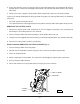
INSTALLING THE CUTTING TOOLS Always push the red STOP button before changing cutters. Slicing, Shredding, Grating, and Julienne Cutting 1. Pull the locking handle forward and swing the feed cylinder out to the rear. 2. Place the ejector plate (Fig. 4) on the knife shaft. Press the ejector plate all the way down and turn until the plate is in the locked position. 3. Select the appropriate cutting tool for the job. Place it on the shaft, turning until engaged. 4.
4. Screw the decoring screw (if using the pusher plate feed attachment) (left-hand thread) OR the agitator device (if using the feed hopper attachment) (left-hand thread) into position in the cutting tool center. 5. Release the catch, swing the feed cylinder back into position, and raise the locking handle. If you use the wrong combination of dicing grid and slicing tool (see Cutting Tool Guide), the following may result: • • The feed cylinder cannot be closed.
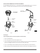
INSTALLING AND REMOVING THE FEED ATTACHMENTS The feed hopper attachment (Fig. 7) is used mainly for cutting round products up to 3" (76 mm) in diameter. The pusher plate feed attachment (Fig. 8) can be used for any type product. FEED HOPPER ATTACHMENT PUSHER PLATE FEED ATTACHMENT AGITATOR DEVICE DECORING SCREW FEED CYLINDER FEED CYLINDER NUTS NUTS TWO INTERNAL GUIDES THREE INTERNAL KNIVES PL-52969 PL-52970 Fig. 8 Fig.
PUSHER PLATE HANDLE FEED HOPPER ATTACHMENT LOCKING KNOB PUSHER PLATE FEED ATTACHMENT SHAFT STOP PAD FEED CYLINDER TUBE PL-52971 FEED CYLINDER TUBE PL-52972 Fig. 9 Fig. 10 Pusher Plate (Use the decoring screw to secure the plates to the knife shaft.) 1. Press the STOP button. 2. Fit the feed cylinder with three internal knives (see Fig. 8). 3. Move the pusher plate handle (Fig. 10) all the way up. 4. Insert the pusher plate attachment shaft (Fig. 10) into the feed cylinder tube (Fig. 10). 5.
USING THE FOOD PROCESSOR When using the feed hopper attachment, bulk product may be added to the feed hopper during operation. When using the pusher plate feed attachment, place prepared products, such as potatoes, carrots, onion, lettuce, cabbage, etc., in the feed cylinder (Fig. 11). When cutting French fries with the Julienne cutter, place/pile the potatoes against one of the internal guides (Fig. 12). The potatoes may be stacked to cut several at one time.
Crimping Slicer 3 ⁄16 CR (4.5 mm) Ripple cuts root vegetables (beets, potatoes, carrots, etc.) Julienne Cutters Julienne Julienne Julienne Julienne Cutter Cutter Cutter Cutter 3 ⁄32 (2.5 mm) ⁄16 (4.5 mm) 7 ⁄32 (6 mm) 3 ⁄8 (10 mm) 3 PL-51799-4 Dicer and French Fry Plates PL-51799-7 The recommended slicer plate will produce near cube-shaped products. The DICER grid dimension must be equal to or larger than the SLICER dimension. DICER 9 ⁄32 (7.
CLEANING WARNING: TURN THE MACHINE OFF AND UNPLUG THE ELECTRICAL CORD BEFORE CLEANING. Clean the machine immediately after each use. Dismantle all removable parts from the machine and wash them in warm water and a mild detergent. Rinse thoroughly and wipe dry with a soft clean cloth. Wipe the exterior of the machine with a damp cloth. Allowing food juices to dry on the machine may cause discoloration.
2. Remove the feed cylinder. The feed cylinder guides (see Fig. 7) OR the three knives (see Fig. 8) may be removed for cleaning by unscrewing the nuts (see Fig's. 7 & 8) with the wrench provided. Rinse all parts with lukewarm water. 3. Remove the cutting tool. 4. If you have used a dicing grid, before removing, push the remaining leftovers through the TOP of the dicing grid with the nylon brush provided. Pushing the leftovers through from the underside of the dicing grid may damage the grid. 5.
TROUBLESHOOTING SYMPTOM POSSIBLE CAUSE SUGGESTED ACTION Machine will not start or stops while operating and won't restart. 1. Machine plug not installed securely into receptacle. Make sure machine is securely plugged into receptacle. 2. Feed cylinder not locked in correct position. Make sure feed cylinder is locked correctly. 3. Feed hopper locking knob not in correct position. Turn feed hopper locking knob counterclockwise to the locked position. 4.
TROUBLESHOOTING (Cont'd.) SYMPTOM POSSIBLE CAUSE SUGGESTED ACTION Cutting tool locked to shaft. Build-up between cutting tool and dicing grid or potato chip grid. Always use the ejector plate. Use a thick leather glove and carefully rotate cutting tool clockwise. Decoring screw or agitator device cannot be removed. Devices have tightened during use of the machine. Use the wrench provided to unscrew devices (left-hand thread). FORM 33966 Rev. A (11-98) – 16 – PRINTED IN U.S.A.