I N S T R U C T INFRARED BOOSTER I O N S INFRARED BOOSTER . . . Gas Water Heaters MODEL IB57 IB140 IB235 IB290 ML-110898 ML-110899 ML-110861 ML-110862 701 S. RIDGE AVENUE TROY, OHIO 45374-0001 937 332-3000 –1– www.hobartcorp.com FORM 34070 Rev.
IMPORTANT FOR YOUR SAFETY WARNING: IF THE INFORMATION IN THESE INSTRUCTIONS IS NOT FOLLOWED EXACTLY, A FIRE OR EXPLOSION MAY RESULT CAUSING PROPERTY DAMAGE, PERSONAL INJURY OR DEATH. DO NOT STORE OR USE GASOLINE OR OTHER FLAMMABLE VAPORS AND LIQUIDS IN THE VICINITY OF THIS OR ANY OTHER APPLIANCE. WHAT TO DO IF YOU SMELL GAS • Do not try to light any appliance. • Do not touch any electrical switch; do not use any phone in your building. • Immediately call your gas supplier from a neighbor's phone.
TABLE OF CONTENTS IMPORTANT FOR YOUR SAFETY . . . . . . . . . . . . . . . . . . . . . . . . . . . . . . . . . . . . . . . . . . . . . 2 GENERAL ............................................................... 4 Delivery Rates at 180°F . . . . . . . . . . . . . . . . . . . . . . . . . . . . . . . . . . . . . . . . . . . . . . . . . 4 INSTALLATION . . . . . . . . . . . . . . . . . . . . . . . . . . . . . . . . . . . . . . . . . . . . . . . . . . . . . . . . . . . . . 5 Unpacking . . . . . . . . . . . . . . .
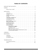
Installation, Operation, and Care of INFRARED BOOSTER GAS WATER HEATERS SAVE THESE INSTRUCTIONS GENERAL The Infrared Booster Gas Water Heaters (available for natural gas or propane) provide 180°F rinse water for commercial dishwashing machines. Health codes and NSF permit 180°F (minimum temperature) water to be used as a sanitizing rinse for utensils and dishware used in restaurants and food-serving operations.
INSTALLATION UNPACKING Immediately after unpacking, check for possible shipping damage. If the Booster Heater is found to be damaged after unpacking, save the packaging material and contact the carrier within 15 days of delivery. Prior to installation, test the electrical service to assure that it agrees with the specifications on the data plate located on the left-front panel of the booster heater.
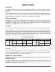
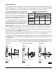
VENTING REQUIREMENTS WARNING: PROVIDE A SCREEN OR BARRIER TO PREVENT PERSONAL INJURY IN AREAS WHERE INADVERTENT PERSONNEL CONTACT WITH THE HOT VENT PIPE CAN OCCUR. Models IB57 and IB140 are Category IV (positive flue pressure, excessive condensate, and flue gas temperature at the heater outlet approximately 330°F). Models IB235 and IB290 are Category III (positive flue pressure, not excessive condensate, and flue gas temperature at the heater outlet approximately 530°F).
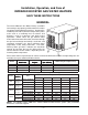
Vent Hood Dishwasher Dish Table or Conveyor Vent Pipe 3 to 4 Inch Adapter Required For IB235 and IB290 PL-53441 Fig. 2 Termination Tee Combustible Sidewall Termination Termination Tee Dish Table or Conveyor Dishwasher 6" Non-Combustible Sidewall Termination Thru-Wall Fitting Termination Tee 6" 3 to 4 Inch Adapter Required For IB235 and IB290 Fig.
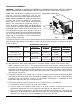
Termination Tee Dish Table or Conveyor Vent Pipe 3 to 4 Inch Adapter Required For IB235 and IB290 PL-53443 Fig. 4 All horizontal runs of the vent pipe shall have a minimum rise of 1/4" per foot of length and should be supported every 5 feet or less (for Canada, every 3 feet) and at every elbow. For horizontal venting of models IB57 and IB140, the total length of 3-inch diameter vent pipe can be up to 70 feet with up to four 90° elbows and one termination vent.
GAS CONNECTION For model IB57, the gas inlet pipe size is 1/2" NPT at the gas valve. For models IB140, IB235, and IB290, the gas inlet pipe size is 3/4" NPT at the gas valve. The gas supply line must be sized to adequately provide the input BTU/Hr rate for that model at the specified flowing pressure (see table). The maximum inlet gas pressure must not exceed the Max value shown in the chart at right. The Min value is for the purposes of input adjustment. The gas valve (Fig.
WATER REQUIREMENTS Proper water quality can improve ware washing performance by reducing spotting, lowering chemical supply costs, enhancing effectiveness of labor, and extending equipment life. Local water conditions vary from one location to another. The recommended proper water treatment for effective and efficient use of this equipment will also vary depending on the local water conditions. Ask your municipal water supplier for details about local water specifics prior to installation.
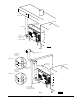
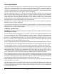
SHOWN WITH OPTIONAL WATER HAMMER ARRESTOR KIT Union Water Shock Absorber Ball Valve 180 F to Dishwasher Pressure Gauge 140 F Inlet Floor Drain Union Ball Valve Pressure Regulator PL-53294 Fig. 6 The heater is equipped with a pump which circulates water inside the booster heater and maintains a uniform water temperature in the tank.
ELECTRICAL CONNECTIONS WARNING: ELECTRICAL AND GROUNDING CONNECTIONS MUST COMPLY WITH APPLICABLE PORTIONS OF THE NATIONAL ELECTRICAL CODE AND/OR OTHER ELECTRICAL CODES. WARNING: DISCONNECT THE ELECTRICAL POWER SUPPLY AND PLACE A TAG AT THE DISCONNECT SWITCH INDICATING THAT THE CIRCUIT IS BEING WORKED ON. The electrical power supply requirement for the heater is 120 Volts, 60 Hz, 1 Phase. Minimum conductor ampacity and maximum protective device should be rated 15 Amperes.
– 13 –
START UP PROCEDURES — FOR YOUR SAFETY READ BEFORE OPERATING Filling the Booster Piping Fill the booster heater with water, purging all air. Make sure water is flowing through the booster to the dishwasher's fill or final rinse before lighting the booster heater by either leaving the main power switch off on Stand Alone units or leaving the manual gas valve closed on Dishwasher Activated units. Checking the Circulator • Before lighting the heater, make sure the water pump is operating properly.
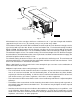
Hot Surface Ignition Using the Robertshaw Gas Valve 1. STOP! Read the safety information. Model IB57 2. Turn off all electrical power to the appliance. 3. Remove the left side panel. 5. Turn the gas control knob clockwise the "OFF" position. Gas Valve Gas Control Knob 4. This appliance is equipped with an ignition device which automatically lights the burners. DO NOT try to light the burners by hand. to 6. Wait five (5) minutes to clear out any gas.
OPERATION The booster heater is designed to deliver 180°F water, up to the gallons per minute and gallons per hour ratings specified in the table on page 4, depending on the incoming water temperature and Booster Heater model and its input BTU/Hr. Provided the necessary power, water, gas, and vent connections are completed, a STAND ALONE unit is started by the activation of the On / Off Switch located on the front (Fig. 9).
MAINTENANCE LUBRICATION The water pump motor and the combustion air blower motor are permanently lubricated and require no other maintenance. VENT SYSTEM Annually check the vent system for obstruction. Check for signs of deformation in the vent pipes which will be an indication of abnormal conditions in the venting system. Refer to the instructions supplied by the vent pipe manufacturer.
LIST OF REPLACEMENT PARTS When ordering parts, be sure to provide the Model Number, ML Number, and Serial Number from the data plate located on the left-front panel of the booster heater. NOTE: As continued product improvement is a policy of the manufacturer, part numbers may change without notification. For the latest part numbers, contact your Hobart-authorized service office.
Components (Pump Side) continued PART No.
Components (Pump Side) continued PART No.