I N S T MODEL 4732 CHOPPER R U C T I O N S 4732 & 4732A CHOPPERS MODEL 4732 ML-18887 (Painted, Non-removable Pan) ML-19282 (SST, Non-removable Pan) 4732A ML-19689 (Painted, Removable Pan) ML-19690 (SST, Removable Pan) 701 S. RIDGE AVENUE TROY, OHIO 45374-0001 937 332-3000 www.hobartcorp.com FORM 34747 (Feb.
Installation, Operation and Care of 4732 & 4732A CHOPPERS SAVE THESE INSTRUCTIONS GENERAL The 4732 and 4732A Choppers are equipped with a 3 HP motor that rotates the worm at 151 RPM. The 4732 and 4732A are designed to use a #32 size knife and plate. Knives and plates, available at extra cost, are not included with the chopper. The stainless steel feed pan on the 4732 is not removable and must be cleaned in place.
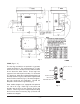
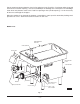
Fig. 1 LEGS (Figs. 1, 2) The four leg assemblies are packed in a separate carton for shipment. The standard legs (53/8" high) allow the rim of the feed pan on the table model to be 27" above the table surface. These legs have neoprene feet and require assembly. To assemble 53/8" high legs: Slide the Leg Stud through the Leg End Cap and the Leg; then thread the Leg Stud into the base of the machine (Fig. 2). Do not overtighten; the legs need only be hand-tight.
ELECTRICAL CONNECTION WARNING: ELECTRICAL AND GROUNDING CONNECTIONS MUST COMPLY WITH THE APPLICABLE PORTIONS OF THE NATIONAL ELECTRICAL CODE AND/OR OTHER LOCAL ELECTRICAL CODES. WARNING: DISCONNECT ELECTRICAL POWER SUPPLY AND PLACE A TAG AT THE DISCONNECT SWITCH INDICATING THE CIRCUIT IS BEING WORKED ON.
Cut the meat into chunks about the size of a fist and place in the Feed Pan. Feed meat under the guard and into the Feed Pan opening. Use the Feed Stomper to dislodge over-sized pieces or to dislodge meat which may become stuck in the Feed Pan opening or the cylinder opening. It is not necessary to force meat through the chopper. When the product is run through the chopper a second time, more speed is attained by feeding small quantities at a time. Allow the machine to feed at its own rate.
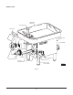
MODEL 4732A REMOVABLE FEED PAN FEED STOMPER DEFLECTOR PLATE MACHINE DATA PLATE KNIFE JUNCTION BOX WORM CYLINDER OIL DRAIN PLUG ADJUSTING RING FEED PAN LOCKING KNOB OIL-FILL PLUG PLUG BUTTON START - STOP SWITCH KNOB Fig.
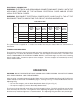
CLEANING (Fig. 3 or Fig. 4) WARNING: DISCONNECT ELECTRICAL POWER SUPPLY AND PLACE A TAG AT THE DISCONNECT SWITCH INDICATING THE CIRCUIT IS BEING WORKED ON BEFORE CLEANING, SERVICING OR REMOVING PARTS. The chopper should be thoroughly cleaned at the end of each day or any time it is not to be used for an extended period of time. On model 4732A only, rotate the Feed Pan Lock Knob counterclockwise to unlock the pan (Fig. 5).
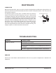
MAINTENANCE LUBRICATION During normal operation, gear case oil may require changing due to condensate mixing with the oil. Gear case oil that has mixed with condensate water will have a milky brown color. If this is present, the oil should be replaced. To change the gear case oil, place a suitable catch pan under the machine and remove the Drain Plug (Fig. 3 or Fig. 4). When old oil is completely drained, replace the Drain Plug.