™ Wingspan: 60 in [1524mm] Wing Area: 660 sq in [42.6dm2] Weight: 5.5 lbs [2495g] Wing Loading: 19 oz/ sq ft [58 g/dm2] Engine: .40 cu in [6.5cc] two-stroke Radio: 4-channel, 4 servos See more of our products at www.hobbico.com WARRANTY Hobbico® guarantees this kit to be free from defects in both material and workmanship at the date of purchase. This warranty does not cover any component parts damaged by use or modification.
Join the AMA (Academy of Model Aeronautics). In addition to other vital functions, the AMA, the governing body of model aeronautics in the United States, provides insurance to members who comply with the Safety Code. You must be a member to fly at R/C clubs chartered by the AMA–most of which are. The AMA can also direct you to the closest club whose membership should have qualified flight instructors. To join the AMA, telephone, write or fax them at the address below, or join on-line at www.modelaircraft.
to make the CA harden right away. Activator (also known as “accelerator”) is usually sprayed out of a small bottle. Additional Items Required One accessory recommended for applying CA is CA Applicator Tips (HCAR3780). These small tips fit on the top of the bottle and help direct and control the amount of CA that comes out. When the tip becomes clogged, just cut off the end and keep going. After the applicator tip becomes too short, just replace it with another.
❏ ❏ ❏ ❏ ❏ Epoxy brushes (6, GPMR8060) Mixing sticks (50, GPMR8055) Mixing cups (GPMR8056) Builder’s Triangle Set (HCAR0480) Precision Magnetic Prop Balancer™ (TOPQ5700) Kit Inspection Field Equipment Before beginning assembly, inspect the parts in this kit to make sure they are of acceptable quality. If any parts are defective or damaged, or if you need assistance with assembly, contact Product Support. Hobbico Product Support: Phone: (217) 398-8970 Fax: (217) 398-7721 E-mail: airsupport@hobbico.
Parts List 1 3 2 6 5 4 1 14 14 9 5 13 7 8 10 6 15 12 11 ❏ ❏ ❏ ❏ ❏ ❏ ❏ ❏ ❏ ❏ 1. 2. 3. 4. 5. 6. 7. 8. 9. 10.
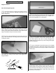
Assemble the Wing Hinge the Ailerons Start with the right wing first. ❏ ❏ 1. Carefully remove the masking tape holding the aileron to the wing. Also remove the protective foam block on the aileron torque rod. ❏❏ 5. Remove the aileron from the wing and take out the hinges. Cut a small strip of covering from the hinge slots in the aileron and the wing between the slits you cut. Hint: Use a small metal straightedge as a cutting guide. ❏ ❏ 2.
❏ 3. Lay one wing panel flat on your workbench. Measure the distance between the bottom of the raised end of the wing and the workbench. The measurement should be 3-1/4" to 4-1/4" [80mm to 110mm]. ❏❏ 9. Position the aileron so there is a small gap between the aileron and the wing–just enough to see light through or to slip a piece of paper through. Add six drops of thin CA to the top of each hinge. Wait a few seconds between drops to allow the CA to fully soak in so it does not get into the gap.
❏ 3. Use wire cutters to cut two of the arms off a four-arm servo arm. Install the arm on the aileron servo. ❏ 4. Drill 1/16" [1.6mm] holes through the servo mount for the ❏ servo mounting screws, then temporarily mount the servo using the eyelets, rubber grommets and screws that came with it. Remove the screws, add a few drops of thin CA to the holes, allow to fully harden, then remount the servo. This process is important to harden the “threads” in the wood so the screws remain tight. 7.
❏ 2. Mount the wheels to the landing gear with a 5/32" wheel collar on both sides of each wheel. Add a small drop of nonpermanent thread locking compound (such as Great Planes Threadlocker GPMR6060) to two 6-32 set screws and thread them into the collars using a 1/16" hex (“Allen”) wrench. Position the wheel collars, then tighten the set screws. Be certain the set screw in the outer wheel collar is in the flat spot. ❏ 7. Disconnect the pushrod from the torque rod horn.
Mount the Stab and Fin ❏ 1. Use 30-minute epoxy to securely glue in the 1/4" [6mm] wing dowels. The longer dowel goes in front. After positioning the dowels, lightly coat them with epoxy so they will be fuelproofed. ❏ 4. Use a fine-point felt-tip pen to mark both ends of the stab where the leading edge meets the tip under the covering. ❏ 5. Measure the distance between the fuselage and the marks on both sides of the stab. Adjust the stab until both measurements are equal and the stab is centered. ❏ 2.
into the balsa beneath. Cutting too deep will weaken the structure, possibly causing the stab to break during flight. An alternate way to cut the covering over the stabilizer is to use a soldering iron. This way, you will not risk accidentally cutting into the balsa. A fine soldering tip is not necessary, but does work best. Using a metal straightedge as a guide, move the soldering iron just fast enough to melt through the covering.
followed by the metal plates and the screw. Bend one of the tubes upward so it will be near the top of the tank when the stopper is inserted. This tube will be connected to the muffler and serves both as an overflow line (to signify when the tank is full) and as a pressure line to provide muffler pressure to the tank. Connect the clunk to the other tube with the silicone tube that came in the tank.
❏ 3. Guide the tubes through the holes up through the fuselage into the radio compartment. ❏ 9. Mount the radio tray in the fuselage with the #2 x 3/8" [10mm] screws. Mount the Servos ❏ 1. Make two 18" [460mm] pushrod tubes from the 3/16" [4.8mm] gray pushrod tubes supplied with this kit. (It doesn’t matter which tubes you cut them from as there will be plenty of tubing leftover anyway.) Thoroughly roughen both ends of the tubes with coarse sandpaper so glue will adhere.
mounting the horn. Mount the horn with two 2-56 x 1/2" [13mm] screws and the mounting plate. arm, to a hole that is as close to 17/32" [13mm] as possible). Secure the connector with a nylon retainer. ❏ 7. Place the servos in the servo tray as shown in the photo at step 5. Drill 1/16" [1.6mm] holes through the servo tray for mounting the servos. Mount the servos in the tray with the screws that came with the servos. ❏ 8. Remove the screws and the servos.
the servo tray as shown. Use thin or medium CA to glue the pushrod tubes to the brace and the fuselage where they exit. Let’s hook up the throttle... ❏ 17. Cut a 12" [300mm] pushrod tube from any remaining 3/16" [4.8mm] gray pushrod tubing. Roughen one end of the tube with coarse sandpaper so glue will adhere. Guide the pushrod tube through the hole in the firewall and through the fuselage until 1/8" [3mm] of the roughened end protrudes from the firewall. ❏ 18.
Prepare the Model for Flight The batteries must be charged to continue. Check the Control Directions The first thing that has to be done is to center the controls and make sure they all move in the right direction. ❏ 1. Connect the aileron servo wire coming from the wing to the servo wire coming from the receiver. Temporarily place the wing on the fuselage. ❏ 4. Move the right control stick on the transmitter to the right as shown in the diagram. Observe the ailerons.
Note that pulling the elevator stick back moves the elevator up (which, in flight, pushes the tail down, thus increasing the angle of the wing thereby making the model climb). The best way to keep this in mind is to think in terms of a pilot in an airplane. He pulls the control stick back to “pull up” the nose of the plane. ❏ 3. Place the end of a ruler on your workbench and hold it up to the elevator. Move the elevator all the way up by moving the control stick on the transmitter.
Control Throws Chart: Ailerons: 7/16" [11mm] up 7/16" [11mm] down Elevator: 1/2" [13mm] up 1/2" [13mm] down Rudder: 1" [25mm] right 1" left [25mm] left ❏ 1. With the transmitter and receiver on, move the throttle trim lever and the throttle stick all the way down. Rotate the arm on the carburetor to fully close the carburetor. Insert a 4-40 x 1/4" [6mm] screw in the screw-lock pushrod connector in the throttle servo arm and tighten the screw to lock the throttle pushrod. ❏ 6. Center the nose wheel.
❏ 4. If you are not able to achieve these settings, more or less movement may be required from the throttle pushrod. The same as the control surface throws, this is done by relocating the screw-lock pushrod connector on the servo arm to another hole, or by relocating the clevis on the carburetor arm to the other hole. ❏ on the landing gear as shown.
Check List Now it’s time to do a final check before taking the model to the field. Take the time now to do these checks and make certain your model is ready to fly. ❏ ❏ ❏ ❏ 3. Mount the wing on the fuselage with four rubber bands. Lift the model on both sides of the fuselage with your fingertips between the lines you marked on the bottom of the wing. ❏ ❏ ❏ ❏ ❏ 4. If the fuselage will rest level with your fingertips anywhere between the lines, the C.G. is correct.
Spare Parts: ❏ 10 x 6 Propellers ❏ Glow plug ❏ #64 Rubber bands (stored in container with talcum powder or kitty litter) in a container with talcum powder or clay-type kitty litter to absorb oil and keep them fresh for the next flying session. If the rubber bands you will be using are different from those recommended, consult an experienced modeler to make certain they are strong enough, and that you have used enough of them. If uncertain, force the front of the wing off of the wing saddle.
by the model and tell you what the controls are doing to confirm that they operate correctly. You should be able to walk approximately 100 feet from the model and still have control without any “glitching” or inadvertent servo operation. Flying The following flying instructions are in no way an endorsement for learning to fly on your own, but are printed so you can know what to expect and what to concentrate on while learning under the tutelage of your instructor.
throttle back to slow the model, thus giving you time to think and react. The SuperStar should fly well at half or slightly less than half-throttle. Adjust the trims so the plane flies straight and level. After flying around for a while, and while still at a safe altitude with plenty of fuel, practice slow flight and execute practice landing approaches by reducing the throttle further to see how the model handles when coming in to land. Add power to see how the model climbs as well.
BUILDING NOTES Kit Purchased Date: _______________________ Date Construction Finished: _________________ Where Purchased:_________________________ Finished Weight: __________________________ Date Construction Started: __________________ Date of First Flight: ________________________ FLIGHT LOG