
Instruction manual


EN
5
RTF / BNF
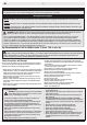
Setup for Optional
Transmitter
Transmitter Thro Aile Elev Rudd
Gear/
Ch 5
Aux
1
Flight Mode/ Panic Switch
SAFE Flight Modes
Supported
DX4e (2pos) N N N N N N/A Default 2 pos Flight Mode
DX4e (3pos) N N N N N N/A Default 3 pos Flight Mode
DX5e (2pos) N N N N N N/A Default 2 pos Flight Mode
DX5e (3pos) N N N N N N/A Default 3 pos Flight Mode
DX6i N N N N R N (Flap System) Norm UP Arrow 100 Land Down Arrow 100 2 pos Flight Mode
DX7 N N N N N N
(Flap System) Norm Down Mid 0 Land UP 100
(3 pos Aux1 switch–0 & 1 are normal, 2 is panic)
2 pos Flight Mode
DX7s N N N N N R
(Switch Select) Gear to INH, FM to INH, Flap to Gear,
Trainer to Aux1
3 pos Flight Mode
DX8 N N N N N R
(Switch Select) Gear to INH, FM to Gear, Flap to INH, Trainer
to Aux 1
3 pos Flight Mode
DX9 N N N N N R (Channel Input Config) Gear is B, Aux1 is switch i 3 pos Flight Mode
DX10t N N N N N R (Channel Input Config) Gear is A, Aux1 is R stick 3 pos Flight Mode
DX18 N N N N N R (Channel Input Config) Gear is B, Aux1 is switch i 3 pos Flight Mode
N=NormalR=Reverse
• SAFEFlightmodeisselectedusingChannel5signal(high,middle,low)
• PanicmodeisselectedwithChannel6signal(high,low)
• Refer to your transmitter’s manual for more information about transmitter setup
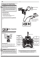
Binding Procedure Reference Table
1. Make sure the transmitter is powered off.
2. Make sure the transmitter controls are
neutral, the throttle and throttle trim
are in the low position, and the aircraft
is immobile.
3. Install a bind plug in the receiver bind
port.
4. Connect the flight battery in the
aircraft. The receiver LED will begin to
flash.
5. Power on the transmitter while holding
the transmitter bind button.
6. When the receiver binds to the transmit-
ter, the light on the receiver will turn solid
and produce a series of three ascending
tones. The tones will indicate the ESC
is armed, provided the throttle stick and
throttle trim are low enough to trigger
arming.
7. Release the Bind button and remove
the bind plug from the receiver.
8. Confirm that the aircraft is bound by
moving controls.
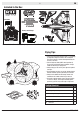
Transmitter and
Receiver Binding
Binding is the process of programming the receiver to
recognizetheGUID(GloballyUniqueIdentier)codeofa
single specific transmitter.
Youneedto‘bind’yourchosenSpektrum
™
DSM2/DSMX
technology equipped aircraft transmitter to the receiver
for proper operation.
Pleasevisitwww.bindny.comforacompletelistof
compatible transmitters.
BIND PLUG
TooperatetheSAFE™systeminthisaircraft,setup
youroptionalDSM2
®
/DSMX
®
transmitter using the chart
below.
Atransmitterwitha2-positionchannel5switchwillonly
allowtheuseofposition0orposition2ightmodes.
Ifpossible,assignchannel5inyourtransmittertoa3-
positionswitchtooperateall3ightmodes.
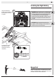
The receiver should retain the binding instructions received from the
transmitter until another binding is done.
YourDeltaRayshouldalreadybeboundtoyour
includedDX4ETX.IFyoueverneedtorebind,
followthesteplistedbelowintheBinding
ProcedureReferenceTable.