ONTOUR • DE LUXE • DE LUXE EDITION • EXCELLENT • PRESTIGE • PREMIUM • LANDHAUS OPERATION GUIDE Version 8 / 2015 GB
1. Introduction Dear Caravaner, Congratulations on the purchase of your new HOBBY Caravan. The trust you have placed in us is both an incentive and an obligation to continuously implement new ideas, technical innovations and fine touches to make our caravans even better. Our fully fitted and highly sophisticated models enable us to offer you the perfect setting for the most enjoyable days of the year. Please read this manual carefully, even if you have been driving a caravan for a longer period of time.
Table of Contents 1. Introduction 1 Introduction 1.1 General information..........................................................................................................................1 1.2 Markings in these operation instructions.........................................................................................2 2 Safety 2.1 Intended use.....................................................................................................................................4 2.
1. Introduction 7.5 7.6 Contact plan for the light control system.......................................................................................76 Special Lighting..............................................................................................................................77 8 Water 8.1 General information........................................................................................................................78 8.2 Water supply.......................................
1. Introduction 1.1 General information Our caravans are continuously being further developed. Please understand that we reserve the right to make changes to their equipment, shape and technology. These operating instructions also describe equipment which may vary from the standard scope of delivery. Therefore, HOBBY shall not be liable for any claims arising from the contents of this handbook. Please understand that we cannot describe all of the individual variations.
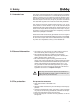
1. Introduction 1.2 Markings in these operation instructions 1 The handbook explains the caravan as follows Texts and illustrations The texts which accompany illustrations are found directly to the right of the illustrations. Details in illustrations (here: entry door) are . marked with position numbers j Indicating details with the help of position numbers Lists - Lists are based on key points and are preceded by a dash.
1. Introduction Optional Extras You have selected a caravan that is equipped to taste. This user manual describes all of the models and equipment offered within the same programme. Therefore, it may include equipment that you have not selected. * Differences and, thus, all of the optional extras are marked with an asterisk. Should there be any equipment or model that is not described in this user manual, please note the enclosed additional operating instructions.
2. Safety 2.1 Intended use This camper has been designed as a mobile travel accommodation for private, not commercial use. It is not intended for permanent residence. Furthermore, no more than the number of people for which this camper has been planned may spend the night in the vehicle. When the camper is on the road, it may only be used in accordance with road traffic regulations and national vehicle safety standards.
2. Safety • Place a fire cover near the gas cooker. • Keep all escape routes clear. • Ensure that everyone is familiar with the fire prevention measures on site. Fighting a fire • Evacuate all passengers immediately. • Close the main shut-off valve on the gas bottle as well as the shut-off valves on gaspowered appliances. • Shut off the electrical supply • Sound alarm and call the fire department. • Only fight the fire yourself if this is possible without risk.
2. Safety 2.4 Emergency equipment To be prepared in case of an emergency, you should always carry the three emergency devices on board and familiarize yourself with them. First-aid kit The first aid kit should always be kept handy. It should have a fixed place in the base vehicle/camper. Any objects removed from the first-aid kit should be replaced immediately. Expiry dates should be checked regularly.
2. Safety 2.5 Before the journey 2.5.1 What to observe before your first drive Vehicle registration Every vehicle which uses public roads is subject to registration. This includes your new caravan. You can register the caravan at your local registration office.
2. Safety Fit for a Speed of 60 mph 1. Your HOBBY caravan is technically equipped for a maximum speed of 60 mph. Under no circumstances may this speed be exceeded! 2. Note the permissible maximum speeds for trailer carriages in the country in which you are travelling! "100" speed sticker 3. Road traffic regulations in Germany were changed on 22 October 2005. Your caravan was already set to a speed of 100 at the factory, and this has been entered in the caravan's registration documents.
2. Safety 2.5.2 Before each drive Road safety • Before driving, check that the signalling and lighting systems and brakes function correctly. • If the vehicle has been standing for a longer period of time (approx. 10 months) have an authorised workshop check the brake system and the accelerator system. (see also Chapter 14.5) • In winter, the roof must be cleared of snow and ice before driving. • Regularly check the tyre pressure before driving.
2. Safety Interior You must also prepare the interior of the vehicle Preparing the interior: • Sort all loose objects and store them in their respective com- partments. • Store heavy and / or voluminous objects (e.g. radio, outer tent, beverage cases) safely before you start your journey, securing them to prevent them from shifting. • If necessary, redirect refrigerator to 12-volt operation. • Shut off all interior lighting.
2. Safety Driving around curves Your carriage is considerably longer than a car. Rules for driving around curves • Do not take curves too quickly or too sharply! • Take the curve at a somewhat wider radius when turning. • Note that the caravan can sheer out of line over the rear. Brakes A trailer carriage behaves differently from an individual vehicle while braking. Therefore, it is advis-able (especially for inexperienced drivers) to conduct several braking tests on a suitable surface.
2. Safety Rules for driving in reverse • The caravan tilts in the opposite direction in which you steer. • Use a guide when driving in reverse. Shunting (moving caravan by hand) Your carriage is significantly larger than a car. Rules for moving caravan • There is a significant blind spot when moving the caravan, even when the exterior mirrors are properly adjusted. • Use a another person when turning into difficult parking spots. Front manoeuvring handle 2.
2. Safety Redirecting electrical devices Rules for redirecting electrical devices • Open the main shut-off valve on the gas bottle as well as the shut-off valves on the gas-powered appliances you require. • Redirect the refrigerator from 12 V to gas or 230 V.
3. Chassis 3.1 General information Frame parts and axles are components of the undercarriage. No technical modifications are allowed; otherwise, the terms of operation are no longer valid! Technical changes are possible only with the manufacturer released . For the sake of traffic safety, the vehicle undercarriage must be maintained just as conscientiously as the base vehicle itself. This maintenance should be carried out by your HOBBY dealer.
3. Chassis 3.3 Loading 3.3.1 General information Rules for loading: • Spread the load evenly between the left and right-hand side of the caravan. Heavy or bulky objects belong in the lower storage compartments and near the axle. • If your caravan has a tandem axle: distribute the centre of weight between the two axles. • Never focus the load in the caravan to the rear (danger of swinging back and forth). • Store baggage in the interior in cupboards and storage com partments.
3. Chassis 3.3.2 Drawbar load You will only achieve optimum driving stability and decisively increase your safety on the road if the drawbar load has been properly adjusted for your combination of base vehicle and the caravan being pulled. The drawbar load indicates the power the caravan's drawbar exerts on the car's clutch.
3.
3. Chassis If the vehicle does not hold the equipment and liquids set out in the table in Item 2 (mass when ready to drive), the loading capacity/additional load (Item 5) can be increased by this value. 3.4 Safety coupling WS 3000 The caravan has been fitted with a safety coupling with tracking stabiliser to prevent it from becoming pendulous or pitching. This system conforms to ISO 11555-1. It has been permitted for use up to a maximum speed of 100 km/h.
3. Chassis 4 Inspection of hitch • The ball coupling is closed when the lever rests in positi on or and the green pin of the hitching display is visible. k l m If the WS 3000 is not properly attached to the coupling ball, the caravan can detach from the base vehicle. It must not be possible to release the ball coupling from the coupling ball when the front landing wheel is lowered.
3. Chassis 3.5 Front landing wheel Rotating it upwards and securing it 4 2 • Hitch the caravan to the base vehicle, aligning the front landing wheel to the rear end of the caravan. • Loosen the tommy screw . • Pull the spindle tube up as far as possible. • Tighten the tommy screw . • Turn the crank of the front landing wheel clockwise to raise the wheel as far as possible and secure it to prevent it from twisting.
3. Chassis Rapid-emergency brake The rapid-emergency brake is combined with the hand brake. If the caravan is involuntarily disconnected from the base vehicle, the hand brake will be tightened or moved beyond the dead centre position by the traction force of the rapid-emergency brake . The hand brake will be employed and the caravan will do an emergency brake. This prevents the caravan from continuing to roll without braking after it has been disconnected.
3. Chassis Wheel brakes The following information regarding brake adjustment applies for all models with the exception of Premium vehicles. The wheel brakes that have been used are drum brakes that do not automatically adjust. They have an automatic reverse that is sensitive to the course you drive. The linings of the wheel brakes are wear and tear parts; therefore, they must be checked every 5,000 km or at least once every year.
3. Chassis 3.8 Rotating stanchions 1 In these models, the hexagon head on which to place the crank is located in the rear of the camper above the opening in the lighting beam. The rotating stanchions are located in the front and rear under the caravan. Hexagon head for front rotating stanchions in the De Luxe (Edition)/Excellent/Prestige/ Premium models Turning the rotating stanchions outward • Park the vehicle as horizontally as possible.
4. Wheels, tyres 4.1 Tyres Only use those tyres designated in the registration documents. Other tyre sizes may only be used with the permission of the manufacturer. • Check tyres regularly to ensure that the tread is worn down evenly; check tread depth; check for external damages. • Always use the same make and model of tyres (summer or winter tyres). • Drive carefully on new tyres for a stretch of approx. 100 km to enable them to develop a full road grip.
4. Wheels, tyres 4.3 Profile depth and age of tyres New tyres are needed (at the latest) when the profile depth measures 1.6 mm. The minimum tread depth only guarantees minimum safety while driving! Tyres age even when used rarely or not at all. Tyre manufacturers' recommendation • Change tyres after six years, regardless of profile depth. • Avoid striking curbs, potholes or other obstacles.
4. Wheels, tyres Rules for wheel screws: - wheel bolts must first be checked after a distance of 50 km and then checked during regular maintenance. Please note: Tyre bolts for all 13" + 14" metal wheel rims and all light alloy rims (incl.
4. Wheels, tyres k • In the ONTOUR model, the spare tire* is attached by means of a tommy screw to a special holder in the gas bottle container at the front left-hand side of the camper. The spare tire can be removed after the tommy screw has been unscrewed. l 2 If the caravan has alloy rims, note that the correct wheel screws are used when installing the spare tyre affixed to a steel rim.
4. Wheels, tyres The rotating stanchions may not be used as a jack*! After changing the tyre, the wheel screws must be examined (after a 50 km drive) to ensure that they are tight enough (tighten if necessary). Changing the wheel • Set the corresponding jack* onto the axle pipe of the swinging lever group or on the longitudinal beam in the area of the axle attachmentsof the wheel to be changed. • In campers with a double axle, always position the car jack* underneath the rear axle.
4. Wheels, tyres Tyre repair kit* Do not use the tyre repair kit if the tyre was damaged as a result of driving without air. Small cuts, especially in the tyre tread, can be resealed using the tyre repair kit. Do not remove foreign objects (such as screws or nails) from the tyre. The tyre repair kit can be used as long as the outside temperature is approx. -30° C or higher. There is an expiry date on the tyre repair kit. Therefore, please note this date.
4. Wheels, tyres D Hold the bottle down with the filling tube and then press them together. Press the entire bottle contents into the tyre. Pull the fill hose off and screw the valve insert tightly into the tyre valve with the valve-core remover . j l k Press the entire bottle contents into the tyre on the tyre valve. Insert the plug into E Open the air hose the cigar lighter socket. Then pump the tyres (Fig. ).
5. Exterior structure 5.1 Ventilation and De-aerating Rules for forced ventilation Proper ventilation and de-aerating of the vehicle is a prerequisite for ideal living comfort. A draft-free forced-ventilation system is located in the floor and a forced de-aerating system is located in the ceiling which should not be interfered with. k 1 j We recommend that you open the roof bonnets whenever you live in the caravan.
5. Exterior structure Removing the ventilation grills during maintenance and repair • Push the lock(s) up as far as they will go. • Carefully lift open the ventilation grid on the left-hand side. • Then pull the right-hand side out of the bracket. l The ventilation grills must be firmly mounted while driving or when it is raining. 3 Locks for ventilation grill 4 Heating element A ventilation flap provides the heating element under the floor of the vehicle with fresh air.
5. Exterior structure 5.2 Opening and closing doors and flaps Keys The following keys are provided with the caravan: - Two keys which fit into the following locks: - entry door, - service flaps, - toilet flap. - gas bottle container lid - fresh-water tank lid - Rear Storage Locker (Premium) External entry door To open • Turn the key to the left until you hear the lock open. • Turn the key back to an upright position and pull it out. • Pull on the door handle. • Open the door. To close • Close the door.
5. Exterior structure 1 3 Stable entry door The upper and lower parts of the entry door can be opened and closed separately by opening the door and then unlocking the upper part of the door from the lower part. l l k 2 Stable entry door Unlocking the upper part of the door • Turn the lever 90° to the left and place it in a horizontal position to separate the upper and lower parts of the door. • Open the upper part of the door completely and press it against the outer wall of the vehicle.
5. Exterior structure 1 Pull the plissé and the insect screen on the entry door to the desired position. To open, carefully guide the rail back to the original position in order to fold the plissés correctly. k j 2 Plissé and the insect screen Entry step tread When entering and exiting the vehicle: • Place step tread in front of the entry door to the caravan. • Ensure that the step tread is placed on a level surface; this prevents the step tread from falling over.
5. Exterior structure Gas-bottle container flap ONTOUR To open • Unlatch the lock with the key. • To unlock, turn the knob that has popped out to a vertical position and open the lid of the gas bottle container. j 1 To close • Close the lid of the gas bottle container. • To lock the lid, turn the knob back to its original position. • Latch the lock with the key. j Gas bottle container, ONTOUR model De Luxe/Excellent/Prestige/Premium To open • Unlatch the lock with the key.
5. Exterior structure Toilet flap 1 2 To open • Unlatch the lock • Press the knob j with the key. k and swing the flap to the side. To close • Push the toilet flap to the side until it snaps in. • Latch the lock with the key. j Porta Potti flap 5.3 Roof The following applies for the roof load • Use only standardised and licensed ladders that can be positioned firmly to climb onto the roof. • The roof has not been made for concentrated loads.
5. Exterior structure The caravan has guide rails for skirting in the lower area of the superstructure. Always slide the skirting in from the middle of the vehicle towards the outer edges. Guide rail for skirting The wheel cover has an integrated keder strip for sliding in the mudguard. (protective wind cover not included in the scope of delivery). Wheel cover with integrated keder strip for mudguard 5.5 Bicycle carrier* Please read the separate operating instructions before using the bicycle carrier.
5. Exterior structure Rear-mounted bicycle carrier Alternatively, a rear-mounted bicycle carrier may be selected (except in the Premium and Landhaus models). The driving performance of the camper changes considerably when there are bicycles on the carrier. The speed should be adjusted to these circumstances: • Ensure that full use is made of the permissible drawbar load and corrected accordingly when there are bicycles on the carrier.
6. Interior structure 6.1 Opening and closing doors, flaps and drawers Furniture doors with a locking mechanism Wall cabinets in the kitchen for ONTOUR, De Luxe (Edition), Excellent, Prestige, Landhaus To open • Press the release and pull on the handle to open the door. To close • Use the handle to close the door until you can feel it lock into place. Wall cabinets in the kitchen Mirror cabinets, rear washroom To open • Open the door of the mirror cabinet by pressing the lower edge from behind.
6. Interior structure Furniture doors with magnetic safety catches or press locks To open • Pull firmly on the handle until the flap or door springs open. To close • Press on the flap or handle of the door until you can feel that it is held shut by the magnets or locks into place. Door with press lock Furniture doors with handle Washroom door • Push the handle to open and shut the door. Washroom door handle Furniture doors with knob Wardrobe • Turn the knob to open and shut the door.
6. Interior structure Furniture doors with a soft close function (optional for ONTOUR) Wall cabinets, stowage cabinets, pantry pull-out To open • Use the handle to pull the door upwards. To close • Use the handle to shut the door until the soft-close function automatically brings the flap to its final position.
6. Interior structure 6.2 TV mount * Extendable flat screen TV • To unlock, press the metal rail and, at the same time, extend the TV mount. 230 V power sockets and an aerial socket for the TV and/or receiver are located directly adjacent to the holder. j 1 Extendable flat screen TV Mount for flat screen TV • To unlock, pull the locking pin k up and then pull the mount into the desired position. • To lock, push the mount back to its original position until it locks into place.
6. Interior structure 3 4 1 Hanging table Hanging table To lower • Raise the front end of the table top by approx. 30°. • Pull down the lower part of the table leg , fold it over by 90° and lay it alongside. • Fold out the supporting legs by 90°. • Pull the table top out of the upper wall brackets . • Raise the front end of the table top considerably and hook it diagonally from above into the lower wall brackets . • Place the supporting legs at the front edge of the table top on the floor.
6. Interior structure 6.4 Seating arrangements and sleeping areas The seat groups can be converted into comfortable beds. 2 2 1 1 Converting the Round Seating Arrangement • Remove the seat and back cushions . • Lower the table. (see Chapter 6.3). • Replace the seat cushions and pull them to the middle of the table. • Fill the outside areas with the side back cushions . k j j k Converting the seating arrangement to a bed The rear seat cushions in round seating arrangements remain in place.
6. Interior structure Bed expansion in the seating arrangement* (or model-specific) In some models, the narrow section of the seating arrangement can be widened into a bed. 1 Conversion • Press the pushlock to unlock the flap. • Lay flap fully on the floor in order to raise flap . • Place flap under the stop on flap and hook into place. Pushlock safety catch l l 2 j k k Carry out this procedure in reverse order to convert the bed back into the seating arrangement.
6. Interior structure Partition for sleeping area Release the clip that fastens the partition and slowly and carefully slide the partition along the rail guide to close it. The magnetic lock will automatically lock the partition. j 1 Securing the partition while driving Head rests (Premium)* The head rests can be manually locked into different positions. Depending on your requirements, lift the head rests until they lock into the desired position and press on them lightly to lower them.
6. Interior structure 6.5 Washroom The shower partition in the rear washroom must be securely fastened when driving. To fold the shower partition out • Loosen the pushbutton . • Fold out the handles on the shower partition. • Fold out the shower partition and guide it to the opposite side. k 1 Securing the shower partition while driving j To shut the shower partition • Guide the shower partition back to its original position and fold it up.
6. Interior structure 6.6 External storage locker * In some models with children's beds, the external storage locker can be selected as an option. When converting to an external storage lock, it is important to ensure that the lower children's bed is secured using the fastening provided for this purpose. 1 j All of the equipment carried in the external storage locker must be and suitable retaining securely fastened using the lashing eyes straps.
6. Interior structure Fully adjustable window stays 2 To open • Should there be a locking knob, press it to work the window latch. • Turn all latches j by 90°. • Press the window latch outwards with your hand until it is open as far as you would like. Then use your other hand to tighten the turn screw until you feel the resistance and the window is held in place. k 1 Fully adjustable window stays To close • Loosen the turn screw to allow you to shut the window.
6. Interior structure Front and kitchen windows Sunshades and insect screens are completely integrated and fully adjustable. To close • Move the handle for the sunshade or the latch for the insect screen slowly and evenly to the desired position. Integrated kitchen window To open • Push the shade up slowly and evenly. To combine • Pull the sunshade down slowly and evenly, then pull the insect screen down to the desired position. Combined sunshade and insect screen 6.
6. Interior structure Large roof light Before opening the light, ensure that the area above the opening of the light is free. The light can be opened to an angle of 60°. To open the roof light • Reach into the opening of the crank bag and fold the crank to the user position by pulling it out. Turn the crank clockwise to open the light to the desired position. When you have reached the maximum opening angle you will feel the resistance.
6. Interior structure Roof fan (washroom) The roof fan can be set up either on one or both sides. 2 1 To open • Press the spring lock j diagonally upwards towards the inside of the roof fan until it unhooks from its locking mechanism. At the same time, using the handle k to press the roof fan upwards. To close • Use both handles k to pull the roof fan firmly downwards until both spring locks j have latched into place.
7. Installation of electrical devices 7.1 Safety tips The installation of electrical devices in the HOBBY caravan has been carried out in accordance with the valid regulations and standards. Please note • Do not remove safety tips and warnings on the electrical equipment. • The installation spaces for electrical equipment such as distribution fuse boards, electric power supply, etc., may not be used as additional storage spaces.
7. Installation of electrical devices 1 6 2 7 3 8 4 9 13 15 14 12 5 10 TFT control panel (Premium/Landhaus models or optional extra) 1 Wall light/lighting in the seating arrangement 2 Ceiling light 3 Kitchen lighting 4 Outer tent light 5 Therme / boiler 6 Lighting Ambience 1 7 Lighting Ambience 2 8 Lighting Ambience 3 9 Memory 10 Floor heating* 12 Main switch 13 TFT display: see p.
7. Installation of electrical devices If the ignition of the base vehicle has been switched on, the outer tent light will automatically be switched off. In this case, it cannot be switched on again. Wall lights / lighting in the seating arrangement 1 and Cei ling Lamp 2 • Briefly press the key to switch each lamp on and off. Press longer on the key to regulate how brightly you want the lights to shine.
7. Installation of electrical devices Kitchen light 3 • Press briefly on the key to switch the kitchen light as well as the spots on and off. Kitchen light Therme with LED display 5 • Press the key to switch the therme on and off. An illuminated LED signals that the therme has been switched on. (LED: only standard panel) 12 • When the main switch is pressed, the therme will also be switched off.
7. Installation of electrical devices Remote control bed • Briefly press the key to switch the - ceiling lighting 1 (in the De Luxe model = ceiling light over the bed) (otherwise = ambient interior lighting) - left bed light 2 - right bed light 3 on and off. 1 2 3 Remote controls, bed Press longer on the key to regulate how brightly you want these lights to shine.
7.
7. Installation of electrical devices Soft key menu bar C This is used to access the individual menus of the components. Soft keys The “soft keys” are used to carry out the commands displayed in the lower menu bar (C). For example, they enable access to submenus, increase or reduce the values shown, or represent the Return button (“Back” function). Control knob Like the “soft keys”, the control knob enables easy navigation between the individual menus.
7. Installation of electrical devices Normally, calibration is carried out automatically, whereby neither the charging nor the discharge current may be more than 150mA. The system can be manually calibrated - while using the 230V mains operation or - if no electrical device has been switched on in 12V operation. To do this, the 30A main fuse must be switched off by pressing the button on the battery container (see “Operation via auxiliary battery”). Now the sensor can calibrate itself.
7. Installation of electrical devices TRUMA ULTRAHEAT Heizung TRUMA ULTRAHEAT TRUMA ULTRAHEAT* heating system The temperature level (1-6) and performance level (in watts) are displayed in the menu for the electric auxiliary heating system. The lower menu icon is shown in green when the heating system is in operation. 12:30 09.01.15 12:30 09.01.
7. Installation of electrical devices Heizung ALDE ALDE hot water heating system* The desired room temperature (in ° C), short-term increase in the amount of hot water for taking a shower (in ° C) and the type of operation (gas/electric) are displayed in the menu for the Alde hot water heating system. The lower menu icon is shown in green when 12:30 23,5 °C 18,0 °C the heating system is in operation. 09.01.15 12:30 09.01.15 12:30 09.01.
7. Installation of electrical devices Use the arrow (menu bar C) or turn the control knob to select the desired type of operation (highlighted in yellow). Then use the “On/ Off” function or turn the control knob to activate your selection. Please also observe the descriptions in Chapter 10.5 Alde hot water heating system. 12:30 09.01.15 23,5 °C 18,0 °C ALDE www.alde.se Service Alde http://www.alde.se/support/ Info: Alde App Info menu Information on the device manufacturer is shown here.
on 12:30 09.01.15 23,5 °C 18,0 °C DOMETIC 1-3 16-31 °C 1-3 09.01.15 12:30 23,5 °C 7. Installation of electrical devices 18,0 °C 16-31 °C 12:30 09.01.15 12:30 09.01.15 on 23,5 °C 23,5 °C 09.01.15 23,5 °C DOMETIC 09.01.15 12:30 09.01.15 23,5 °C 2 23,5 °C 18,0 °C 09.01.15 12:30 DOMETIC 09.01.15 http://dometic.com 2 2 The values can be changed using the “+/-” soft keys on menu bar C or by turning the control knob.
7. Installation of electrical devices 01.07.15 14:00 ------- 14:00 Displaying the data in the fixed header A This menu gives an overview of the data in the fixed header A. It is only possible to exit this menu by using the “Back” function; it does not automatically switch back to the main menu on the control panel. ------- 01.07.15 ----- ----- Einstellungsmenü Datum Uhrzeit Temperaturoffset Wecker on/off 01.07.15 14:00 ------- ------- 09.01.
7. Installation of electrical devices WLAN-Module * Hobby's CI-Bus board management can link together up to 15 devices, enabling you to operate them using just one central control panel that shows their functions on its display. (standard) When coupled to a WiFi module, all of the functions on the TFT control panel can be wirelessly controlled via your smartphone, tablet or notebook. The SD card is also found on the WLAN module. The devices are updated on this card.
7. Installation of electrical devices i The current values can be read out here (see also p. 66 for the data from the fixed header A and p. 60 for battery management (only with self-sufficient package). Information The different lights can be switched on and off here. Lighting Devices that are connected to the control panel can also be controlled via the WiFi network. (See also TFT control panel.
7. Installation of electrical devices General information regarding the TFT display The time and date are buffered by a 3V 210 mAh, CR2032 type button cell. If, therefore, the time should be incorrect or the clock should stop working, this button cell must be replaced. It is mounted on the reverse of the circuit board of the TFT display. To replace this button cell, the TFT display must be removed from the furniture front by carefully clipping the chrome-plated frame out of its holder.
7. Installation of electrical devices 1 To set up an electric connection • Pull out the 13-pole plug that connects to the base vehicle. • Switch off the automatic circuit breaker by pressing the rocker button down . • Take hold of the bottom of the cover flap of the CEE external socket and pull it up. • Completely unwind the connector cable. • Open the cap of the CEE connector plug by pulling it up in a 90° angle. • Insert the plug until it locks into place. • Switch the automatic circuit breaker back on.
7. Installation of electrical devices Residual current device 2 The standard version of your vehicle is equipped with a residual current device that will interrupt the electric circuit in case of a possible residual current. Should there be a power failure, the fault current circuit breaker ('fast interrupt' = FI switch) will interrupt the entire 230V electric circuit. Repairs must not be carried out on the residual current device.
7. Installation of electrical devices Operation via base vehicle During the drive, the battery of the base vehicle takes over the supply of the 12 V devices if contact 9 of the 13-pole socket system on the base vehicle has been equipped. Use the main switch on the control panel to switch off the 12 V operation during the drive, on longer stopovers and breaks to conserve power in the base vehicle‘s battery.
7. Installation of electrical devices Operation via auxiliary battery* (self-sufficient package) Charge controller in clothes cupboard on wall Auxiliary battery • Only accumulator batteries with bound electrolytes (gel or AGM batteries) may be installed in those positions specified by the manufacturer. • The installed battery may not be opened. • When changing auxiliary batteries, use only batteries of the same make and capacity. (Setting the battery type on the control panel: see p.
7. Installation of electrical devices A pushbutton is located directly on the battery container. It is used to disconnect the battery from the 12 V electrical system. At the same time, this button serves as a 30 A automatic circuit breaker. j 1 Pushbutton Battery container If the caravan is not used for a longer period of time, please disconnect the battery from the electrical system in order to prevent the battery from being excessively discharged.
7. Installation of electrical devices Assignment of fuses The fuses for the individual internal electric circuits are located in the lighting control module. They are assigned as follows (from left to right): In some models, there may be slight deviations in this assignment.
7.
7. Installation of electrical devices 7.6 Special Lights The switches for the lights described here are located directly on the lights themselves; they are not controlled via the control panel. Corner lights 1 Spotlight separately.
8. Water 8.1 General information We recommend that you inspect any water you have left in the tank, this is very critical before using the water again. • Water that is suitable for drinking should always be used with working with food. This also applies to washing your hands and cleaning the objects that have come into contact with food. • To ensure that the quality of the water is faultless, the water should be taken directly from the public drinking water system.
8. Water 8.2 Water supply Fresh water tank 4 The tank has a volume of 25 or 50 l (model-specific) and is located either under the bed or in the seating arrangement. j The tank is filled with fresh water by means of the filler neck the side wall. 1 Fresh water tank 3 k on The neck for filling up fresh water is marked by a blue cap and a picture of a water tap on the upper edge of the frame.
8. Water Never introduce anti-freeze or other chemicals into the water system. This can be poisonous! When operating during winter ensure that the fresh water tank is sufficiently heated. To remove water • The water will be mixed to the desired temperature according to the position of the pre-mixing unit. Hot water supply • Use the control panel to switch on the therme. The temperature of the water is regulated by means of a thermostat via 230V mains supply to 55° C. • The therme will hold approx. 5 litres.
8. Water Emptying the water system • Use the control panel to switch off the electricity for the water pump by pressing the main switch for a longer period of time (3 - 4 seconds). • Open all of the water taps to the centre setting. • Hang up the adjustable shower head in the shower. • Open the outlet valves on the therme (The therme is located by the queen-sized bed/seating arrangement.). • Unscrew the cap on the cleaning port of the fresh water tank . • Unscrew the overflow pipe in the fresh water tank.
8. Water Rolling waste water tank The rollable waste water tank can be pushed beneath the vehicle when the caravan is stationary. It collects the waste water and holds 24 litres. The waste water tank can be transported on wheels and , allowing you to transport it has an extendable transport handle to the appropriate waste disposal place for emptying.
8. Water 8.3 Toilette 1 2 3 Preparing the excrement tank Before you can use the toilet, you must first prepare the excrement tank. How to do this is shown in Figures 1 to 11 on the left. 4 5 7 8 10 11 12 13 15 18 16 19 6 9 Never add sanitary liquids directly through the valve or into the toilet bowl, because this may damage the washer of the valve in the excrement tank. Always add liquids through the empty-ing support (Fig. 6) We recommend that you press the ventilation button (Fig.
8. Water Using the bench toilet In the control panel above, the flush knob is located on the left and the LED of the filling level indicator on the right. It lights up when the excrement tank must be emptied. k The lever j l for opening the slider is located on the left side. 1 2 3 Pivoting toilet 21 22 23 24 25 26 27 28 29 * 30 31 * Benc toilet apr. 2 ltr. Emptying the excrement tank The excrement tank has a capacity of approx. 19 litres.
9. Gas system 9.1 General safety rules for the use of liquid gas facilities The gas operation pressure is 30 mbar. You are not permitted to operate the heating system while driving. Inspection of the gas facilities • Have the gas facilities checked by an expert before the first use. • The gas facilities should be inspected by an expert every two years.
9. Gas system Regulator knobs and valves Connecting the gas regulator to the gas bottle Positioning the gas bottle in the gas bottle container • Only use those regulator knobs custom-made for vehicles, with a safety valve. Other regulator knobs are not permissible in accordance with the German Association of Gas and Water Experts, worksheet G 607, and EN 1949. They are not sufficient to tolerate the immense strain. • Pressure control devices must have a fixed outlet pressure of 30 mbar.
9. Gas system Never use portable cooking or heating equipment, except for electrical heating equipment (note the power consumption), but not radiant heaters, because these may cause a fire or risk of suffocation. 9.2 Gas supply The caravan is equipped with propane gas facilities.
9. Gas system Changing gas bottles • Open the flap of the gas bottle container. • Shut the main shutoff valve on the gas bottle. • Manually unscrew the gas pressure regulator and gas hose from the gas bottle (left-handed thread). • Loosen the belts and remove the gas bottle. • Place a full gas bottle back in the gas bottle container. • Lash the fastening strap(s) securely. • Manually screw gas pressure regulator and gas hose onto the gas bottle (left-handed thread).
9. Gas system 9.3 External gas socket * The external socket for gas is used to connect external gas devices such as a gas barbecue or lamp. The operating pressure of devices to be connected must be 30 mbar. Maximum performance of devices to be connected: 1.5 kW. The plug connection can only be hitched when the emergency shutoff valve has been closed. Push back the clutch sleeve to undo the safety latch.
10. Built-in devices 10.1 General information In this chapter, you will find information on the devices that have been built into the caravan. This information refers only to the operation of these devices. To some extent, the devices described are special accessories. For further information on the individual built-in devices, please refer to the separate operating instructions that have been included in the blue service bag found in the vehicle. Built-in devices may only be repaired by specialists.
10. Built-in devices To operate 1 Due to its design, the radiator cover gets hot when the heating is on. The operator is responsible for exercising due diligence so that third parties (especially small children) are not hurt. • Open the valve on the gas bottle and the gas shutoff valve on the gas pipe. • Turn the operation handle to the thermo-stat position 1-10. • Press the operation handle down until it locks. The ignition is automatic from this position, until the flame burns.
10. Built-in devices Changing batteries on the automatic ignitor If you cannot hear any ignition sparks or only hear them in intervals of more than one second, then you must insert a new battery. • Ensure that the heating has been switched off. • Remove the radiator cover (see Truma operating instructions). • Push the cover of the battery compartment up and exchange the battery (take special note of plus and minus). • Close the battery compartment. • Reattach the external panel.
10. Built-in devices 10.3 Electric auxiliary heating* The electric auxiliary heating (Ultraheat) operates only when the caravan is connected to the 230V mains supply. The electric auxiliary heating is integrated in the hot-air heating system. This allows for three possible heating methods: - just the gas heater - gas heater + electric heater - just the electric heater The electric auxiliary heating allows you to heat up the vehicle more quickly.
10. Built-in devices 10.4 Electrical floor heating* The heating system is located in the middle walking space of the floor. It is 60 cm wide; the length depends on the type of vehicle. This heating system is not meant to heat the room; instead, it reduces the loss of heat via the floor. To turn on the 24 V floor heating You will find the switch on the service panel. The floor heating operates only when the caravan has been attached to a 230 V power supply.
10. Built-in devices Check the amount of liquid in the expansion tank at regular intervals. When the heating is off, the liquid should be approx. 1 cm above the "Min" mark.
10. Built-in devices D EF G H I C B A J Basic menu K Idle position A. Clock. The clock shows the date and time (when activated). B. *Outside temperature. The outside temperature is displayed. C. Inside temperature. The inside temperature is displayed. D. Circulation pump. This icon is displayed when the circulation pump is in operation. E. Starting the heating system automatically. This icon is displayed when this function has been activated. F. Daytime automatic system.
10. Built-in devices Hot water The boiler can also be used even if it has not been filled with fresh water. 1. No hot water. If you do not need hot water, press "-". (The icon is empty). It is not possible to make any settings for hot water if the daytime or nighttime automatic system is in operation and you have switched off the hot water. The plus and minus icons are then greyed out. 2. Normal operation. If there is fresh water in the tank and you would like to have hot water, press "+".
10. Built-in devices Heating with electricity Use the following procedure to activate the "Heating with electricity" function. The higher the selected output, the faster the camper will heat up. If electricity and gas are selected together, you can set whether gas or electricity is to take priority (see Tools menu). The boiler uses no higher output than is required, even if 3 kW has been selected. 1. Starting and changing the different heating levels step by step (Off, 1 kW, 2 kW or 3 kW) with "+" or "-".
10. Built-in devices 10.6 Boiler * The optional boiler holds approx. 14 litres of water. It heats the water electrically using an integrated heating rod. It replaces the standard Truma therme. Before each journey, make sure the boiler has been switched off and then attach the chimney cap. Before operating the boiler you must remove the chimney cap. Empty the boiler if there is a danger of frost. Never operate the boiler if it is empty.
10. Built-in devices 10.7 Refrigerator If the external temperature is high, full refrigerating capacity can only be ensured by means of sufficient ventilation.To achieve better ventilation, ensure that the side of the camper with the refrigerator ventilator stands in the shade. Please refer to the manufacturer's separate operating instructions before using the refrigerator.
10. Built-in devices 4 3 2 1 Operating the refrigerator 12 V operation 12 V operation can only be used while driving, when the motor is running. When resting or if you have stopped for a longer period of time, turn off the 12 V operation and, if required, select another mode of operation. • Set the energy selection switch to the battery symbol . • 12 V operation will only work when the motor of the base vehicle is running.
10. Built-in devices The freezer compartment is suitable for making ice cubes or for storing frozen food for a short period of time. It is not suitable for freezing food. It is not suitable for freezing food nor for the proper storage of medication. Environmental conditions influence the performance of the refrigeration unit. The system reacts sluggishly to changes in the thermostat regulator, loss of cold when opening the door or storing goods.
10. Built-in devices 10.8 Gas cooker The kitchen segment of the caravan is equipped with a 3-flame gas cooker. Combined sink and cooker Before first use: • Open the bottle valve and the quick-close valve in the gas line. • The roof ventilation or the window must be open while operating the gas cooker. • Operation handles, which must be pressed to ignite gas devices, must automatically spring back into the original position upon release. • The sockets above the cooker may not be used when cooking.
10. Built-in devices Never allow gas to escape without burning. Danger of explosion! After cooking, leave the glass coverj open until the burners stop giving off heat. Otherwise, the glass cover could burst. Do not store easily inflammable objects such as dish towels, napkins, etc., near the cooker. Danger of fire! 10.9 Fume hood* As an option, the kitchen can be fitted with an extractor fan. The built-in fan blows kitchen odours directly outside.
10. Built-in devices 1 2 Operating the oven 3 4 1 Igniter 2 Oven 3 Adjustable knob 4 Grill Please refer to the separate manufacturer's operating manual. Turning on the oven • Switch on the 12 V power supply using the main switch on the control panel. • Open the main shutoff valve on the gas bottle and the gas shutoff spigot marked “oven”. • Open the oven door completely. • Position the baking tray or grill so that it is not in direct contact with the flame.
10. Built-in devices 10.11 Microwave* The kitchen in the camper can be fitted with a 230V microwave, which is installed behind a flap or a sliding door in the kitchen wall cabinet. This device is suitable for defrosting, heating up and cooking food for your personal use. Leave the flap or sliding door open when operating the microwave.
10. Built-in devices 10.12 Rooftop Air Conditioning * The air conditioner is located instead of the roof window on the living room ceiling. To operate the air conditioner correctly and optimize its performance, you should observe the following: Roof air-conditioning system • Ensure sound thermal insulation; seal chinks and cover up glass areas. • Avoid opening doors and windows unnecessarily. • Do not plug or cover up air intakes and openings. • Do not spray water into the air conditioner.
11. Accessories Accessories Note the detailed operation instructions, installation instructions and circuit diagrams from the manufacturers when using accessories. These are located in your service package. • Any changes to the status of the caravan as delivered by the manufacturer may endanger driving performance and roadworthiness. • Any accessories, add-ons, modifications or mounted parts that have not been approved by HOBBY may cause damage to the vehicle and impair its roadworthiness.
11. Accessories Object Weight [kg] Water/gas/electricity 50 litre fresh water tank (instead of 25 l fresh water tank) 28.00 Cable adapter 7/13-pole for connecting cars 0.30 Charge controller for 12 V power supply* with Booster , battery sensor, and battery container 2.80 City water supply 0.50 External socket in outer tent, incl. 230 V output, SAT and TV connection / 12 V switch in the external socket in outer tent 0.40 Gas socket, external 1.50 TFT control panel for lighting system and tank, incl.
12. Maintenance and upkeep 12.1 Maintenance Maintenance intervals fixed maintenance intervals apply to the caravan and the devices installed in it. Rules for maintenance intervals • Have the first maintenance performed by a HOBBY dealer 12 months after the initial registration. • Havve all further maintenance performed once annually at a HOBBY dealer. • Have all maintenance on built-in devices performed in accordance with the corresponding maintenance intervals indicated in the operating instructions.
12. Maintenance and upkeep Greasing and oiling Regularly examine and grease the sliding parts and stationary parts of the chassis. If the caravan is used seldom, yearly maintenance is required. 1 Rules for greasing and oiling • Movable parts such as pins and hinged parts on the hand brake lever and deflexion lever of the ramp should be oiled lightly. • Lightly grease the stationary parts on the case of the overrunning equipment after every 5,000 kilometres of driving.
12. Maintenance and upkeep Changing the friction lining 1 It is very easy to exchange the friction pads when they are worn out. Messrs. Winterhoff offer a corresponding set of spare parts. Please note the detailed instructions for assembly in the manufacturer's spare part kit. j Noises Certain noises can occur during the course of the drive; these noises, however, have no influence on the operative effectiveness of the tension ball coupler. Friction pads Possible causes of these noises can be: 1 1.
12. Maintenance and upkeep 12.4 Changing the taillight bulbs The following description for changing the rear light bulbs refers to the ONTOUR model. Different rear lights are used in the Premium and Landhaus models. Unfortunately, it is not possible to replace these light bulbs easily. In this case, please speak to your dealer, who will be pleased to assist you in changing these light bulbs.
12. Maintenance and upkeep • Unscrew the light bulb a new one. m from the socket and exchange it for 4 Changing the bulb • Carry out this procedure in reverse to put everything back in place, taking care to ensure that the writing on the lamp is not upside down. n 5 If several light bulbs have to be replaced, take care to ensure that the lamps are not accidentally switched and that everything goes back in its original place.
12. Maintenance and upkeep ONTOUR fog tail light • To change the light bulb in the fog tail lamp, unscrew the two screws 10. Change the light bulb 11 and securely fasten the screws 10 to the cover. 10 Loosen the screws 11 Change the bulb Changing the rear light bulbs in the De Luxe (Edition), Excellent and Prestige models • Remove the two screws j 1 Loosen the screws • Remove the rear light from the lighting beam.
12. Maintenance and upkeep • Remove the bulb from the socket by turning it. Carry out this procedure in reverse order to install a new bulb and replace the rear light. Remove the bulbs from the socket Changing the battery and maintenance of the smoke detector* Please observe the operating instructions of the device manufacturer. Maintenance The smoke detector system does not require any maintenance.
12. Maintenance and upkeep Test • Press the test button for at least 4 seconds until the alarm goes off. The alarm goes off when the electronic system is working. It will stop as soon as you let go of the test button. Test the smoke detector every time the battery has been changed. Batteries should never be thrown in the container for normal household waste. Always return used batteries to a shop that sells batteries or take them to a designated collection point. 12.
12. Maintenance and upkeep Direct contact with plastics such as PVC, soft PVC and similar products (e.g. stickers) must be avoided at all cost. It is not possible to avoid transmitting plasticizers when solvent-based contents come into contact with the aforementioned plastics and this causes the parts to become brittle. Cleaning the exterior The vehicle should not be washed more often than necessary. Rules for cleaning the exterior • Rinse the vehicle with a light stream of water.
12. Maintenance and upkeep Do not polish too often since polishing removes the top layer of paint. Frequent polishing causes more damage than it remedies. Rules for treating tar and resin stains • Remove residues from tar and resin as well as other organic stains with petroleum ether or spirit. Do not use aggressive solvents such as products containing esters or ketone. Rules for damage repair • All damage should be repaired immediately to avoid further damage from corrosion.
12. Maintenance and upkeep Cleaning the interior To reduce problems arising from dampness, use water sparingly when cleaning inside. Rules for cleaning seat covers, upholstery covers and curtains • Clean seat covers with a soft brush or vacuum cleaner. • Have heavily soiled upholstery covers, bedspreads and curtains dry cleaned; do notwash them yourself! • Clean with the foam of a gentle detergent if required.
12. Maintenance and upkeep Rules for cleaning the carpet: • Clean with a vacuum cleaner or brush. • If necessary, treat or shampoo with carpet foam. Rules for cleaning PVC surfaces: Sand and dust can damage the surface of a PVC surface that is walked on regularly. When in use, clean the floor daily with a Hoover or broom. • Clean the surface with a special solvent for PVC surfaces. Do not place carpets on wet PVC surfaces. Carpets and PVC surfaces could stick together.
12. Maintenance and upkeep The following applies for built-in equipment: • Heating: remove all of the dust that has collected on the heat exchanger, base plate and fan wheel of the hot-air system at least once a year before the caravan season begins. Clean the fan wheel carefully with a brush or small scrubber. • The glycol mixture in the hot-water heating * system should be replaced every two years, because certain properties such as protection against corrosion deteriorate.
12. Maintenance and upkeep The following applies for tanks and containers: • Clean, disinfect, descale and completely empty all water pipes and faucets. Leave faucets open. • Clean the fresh water tank and empty it by unscrewing the overflow pipe. • Clean and empty the waste water tank. • Clean and empty the toilet flushing tank and the excrement tank. Clean the toilet valve, apply a lubricant for seals and leave it open. • Completely empty the therme/boiler.
12. Maintenance and upkeep Please also refer to the information given by the manufacturers of built-in devices regarding winter. The following applies for ventilation: During operation in winter, condensation is caused when using the caravan in low temperatures. Sufficient ventilation is extremely important to ensure that the quality of the air inside the caravan is good and to avoid damages to the vehicle caused by condensation. • Do not shut vents for forced ventilation.
12. Maintenance and upkeep The following applies for containers: • If the interior is sufficiently heated, the fresh water tank, water pipes and therme/boiler should not freeze. Fill all of the water containers only after the interior has been thoroughly heated. • Since waste water is collected outside the vehicle, add antifreezer or common salt to it. The drain cock of the sewage pipe must be kept clear.
13. Waste disposal / environmental protection 13.1 The environment and mobile travel Environmentally sound use By nature of their activities, caravan users bear a considerable responsibility towards the environment. Therefore, you should always use your caravan in an environmentally sound manner. Rules for environmentally sound use • If you plan to stay longer in cities and municipalities, please park in an area that is specifically marked for trailer combi nations.
13. Waste disposal / environmental protection Rules for trash disposal • Separate trash and bring recycleable materials to the appropriate collection sites. • Empty trash containers in designated areas as often as possible. This prevents unpleasant odours and trash build-up. Rules for rest areas • Always keep rest areas clean, even if the mess was created by others. • Never dispose of your household trash in the containers provided in rest areas.
14.
14. Technical data Landhaus Presige Premium Excellent De Luxe Technical name ONTOUR Trade name De Luxe Edition 14.1 Chassis data g.v.w.r.
14.
14. Technical data 14.2 Possibilities for increasing loads Landhaus Presige Premium Excellent De Luxe Technical name ONTOUR Trade name De Luxe Edition Basic version g.v.w.r.
14. Technical data Maximum increased load g.v.w.r. [kg] Axle load [kg] Axle New ! Additional rear crossbar Wheels New ! Brakes New ! Leading equipment Forked drawbar New ! Weight 1350 1350 no no no no no no 0,0 1350 1350 no no no no no no 0,0 1500 1500 VGB 15 MV 201.340.001 185 R 14 C LI 102 no KFL 20 A no 11,7 1500 1500 VGB 15 MV 201.340.001 185 R 14 C LI 102 no KFL 20 A no 11,7 1500 1500 VGB 15 MV 201.340.
14.
14. Technical data Maximum increased load g.v.w.r.
14. Technical data 14.3 Weights of the vehicles Type Weight empty [kg] Basic equipment [kg] Mass in running order [kg] g.v.w.r. [kg] Add.
14. Technical data Type Weight empty [kg] Basic equipment [kg] Mass in running order [kg] g.v.w.r. [kg] Add.
14. Technical data Landhaus Standard version Presige Premium Excellent De Luxe Technical name ONTOUR Trade name De Luxe Edition 14.4 Tyres and Rims g.v.w.r.
14. Technical data Max. increase (for increased load) Metal wheel rims for increased load Light alloy rims for increased load g.v.w.r.
14. Technical data 650 KMFe B33K Landhaus Presige Premium Excellent De Luxe Technical name ONTOUR Trade name De Luxe Edition Standard version • g.v.w.r.
14. Technical data Max. increase (for increased load) Metal wheel rims for increased load Light alloy rims for increased load g.v.w.r.
14. Technical data 14.5 Tyre pressure values As a rule of thumb, it may be assumed that a filled tyre suffers a loss of pressure of 0.1 bar every two months. Check the pressure regularly to avoid damage to tyres or a burst.
Index Index A Accessories 108 Additional equipment 17 Additional loads 15 Air-circulation fan 92 Airing 117 Auxiliary battery 73 B Basic equipment 17 Bed conversion 45 Bicycle carrier 38 Boiler 99 Brakes 11 C CEE plug 70 Changing the tyre 26 Chassis 119 Checking the gas system 85 Children‘s beds 47 Choosing a parking space 12 Cleaning the exterior 118 Cleaning the interior 120 Clothes cupboard light 77 Control panel 54 Cooker 103 D Definition of masses 16 Doors and flaps interior 33 Doors opening and closin
Index M Maintenance 110 Mass, definition 16 Microwave 106 O Oiling 111 Outer tent light 56 Oven 104 Overrunning brake facility 21 P Plissés 52 Push lock 41 R Rear light bulbs 113 Redirecting electrical devices 13 Refrigerator 100 Registration 7 Regulator knobs 86 Remote control 58 Remote control 58 Rims 25 Roof 37 Roof bonnet 51 Roof fan 53 Roof load 37 Rotating stanchions 23 S Safety tips 54 Securing the vehicle 12 Self-sufficient package 73 Service flaps 35 Shunting 12 Shutoff valves place of installatio
Hobby-Wohnwagenwerk Ing. Harald Striewski GmbH Harald-Striewski-Straße 15 D-24787 Fockbek/Rendsburg www.hobby-caravan.