
User Manual


Step 2: Swap the servo wires
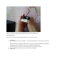
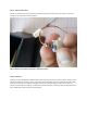
Figure 2 shows the problem…the signal and ground wires are backwards when comparing the HK-5320 to the
walkera servo. This is an easy fix. Just gently pry up on the little white tab holding the servo wire in place, and give
the wire a little tug. It should slip out. Remove both the Yellow and brown wires, swap them, and reinsert. If you
have trouble with this, please stop now…it gets worse.
Fig 2: Walkera connector is on the right, HK-5320 connector is on the left. Swap the outside 2 wires on the HK-
5320 so that the yellow wire will then be on the right, and the brown is on the left (therefore matching the
walkera connector).
Step 3: Open it up
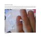
Now we get into the gritty stuff. Open up the servo (one screw on top, one on bottom). Don’t lose the screws!
Inside, you’ll find a motor and a circuit board. The board is what we’re after. There is also a tiny little piece of
clear plastic under the circuit board. Don’t lose that either! I don’t know what it does, but don’t lose it.
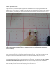
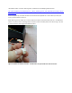
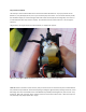
Hold the board as shown in figure 3. You will see 3 wires coming from one side of the board, and running
somewhere deep inside the servo (not the 3 wires going to the connector!). The goal here is the swap the middle
wire and the left wire, when held as pictured. I have seen in other writes ups where the wires are different
colors…sometimes you swap the red/black, sometimes you swap the red/blue. As you can see here, mine are all
blue. You really don’t care what color they are, your goal is to swap the left 2.