
User Manual


Step 4: Swap the motor wires
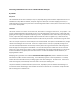
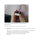
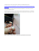
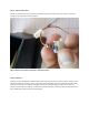
Flip the circuit board over, and you will see two wires running from the board to the servo motor. These wires
now need to be switched. See Figure 5 Below.
Figure 5: Motor to circuit board connection. Swap these 2 wires.
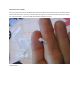
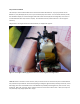
Step 5: reassemble
Congrats! If you’ve swapped the 2 outside wires on the servo connector, the two of the 3 wires as shown in step 2,
and the two motor wires shown in step 3, you’re done with the hard part! Put that tiny little piece of plastic back
under the circuit board, and cram the board back in the servo. Smash everything in, make sure no wires are
pinched, and close the servo back up. You didn’t lose the screws did you? I don’t have a picture of the final servo,
but it should look the same as when you started (duh).