
HWI38010404_Motor_Manual_EN

• Please carefully check power devices and manual of car frame to ensure the power pairing is
reasonable. Avoid wrong pairing to overload and damage the motor.
• Always wire up all the parts of the equipment carefully. If any of the connections come loose as a
result of vibration, your model RC may lose control.
• Never apply full throttle if the pinion is not installed. Due to the extremely high RPMs without load,
the motor may get damaged.
• Never allow the motor case to get 100 degrees Celsius (212 degrees Fahrenheit) because the
magnets maybe demagnetized by high temperature.
Warnings
Thank you for purchasing this HOBBYWING product! The power of brushless power system is
powerful. Any improper use may cause personal injury and damage to the product and related
devices. We strongly recommend reading through this user manual before use and strictly
abide by the specified operating procedures. We shall not be liable for any liability arising from
the use of this product, including but not limited to reimbursement for incidental or indirect
losses. Meanwhile, we do not assume any responsibility caused by unauthorized modification
of the product. We have the right to change the product design, appearance, performance
and use requirements without notice.
CAUTIONS
ATTENTION
ATTENTION
01
02 Features
03 Specificati ons
Model
PN
KV Value
Lipo Cells
Resistance
No-load current
Outer Diameter/Length
Shaft diameter/Exposed shaft length
Bearing size(mm)
Pole
Weight
Application
30402800
2250KV
3-6S Lipo
0.0048Ω
5.0A
42mm(1.654in) / 78mm(3.071in)
5mm(0.197in) / 18.5mm(0.728in)
Front: D16*D5*T5 Rear: D11*D5*T5
4
455g
1/8 Truck, Monster Truck
EZRUN 4278SD G2
30402751
2500KV
3-4S Lipo
0.0065Ω
4.8A
42mm(1.654in) / 68mm(2.677in)
5mm(0.197in) / 18.5mm(0.728in)
Front: D16*D5*T5 Rear: D11*D5*T5
4
355g
1/8 Buggy, 1/10 Heavy-duty Monster Trcuk
EZRUN 4268SD G2
USER MANUAL
EZRUN 4278SD/4268SD G2
Sensored Brushless Motor
20220304
• Chip built in the motor,when matched with Hobbywing EZRUN MAX8 G2 esc, it not only has perfect compatibility, the ESC can automatically identify the motor and build a pure/full sensor mode power system, providing better
manipulating performance and more delicate manipulating feel.
• The rotor adopts four strong magnetic and high temperature resistant sintered Nd-Fe-B magnets, widens the magnetic tile, provides super torque, and makes the motor have strong explosive force and stable output power.
• The independent high-precision encoder always outputs pure rotor position signal, which effectively avoids the interference of sensor signal and makes the motor work stably in sensor state.
• High output efficiency, effectively reduce the motor temperature and output more power under the same load.
• CNC machined aluminum housing, high purity copper windings, advanced rotor structure, 0.2mm silicon steel laminations, high-quality stainless steel output shaft, high-precision bearing for high durability and smoothness.
• The innovative new sensor interface and rubber cover bearing have better waterproof and dustproof effect than the traditional sensor motor.
78 ± 0.318.5 ± 0.5
40.8
5
4.5 Cut
14.5
4-M3 4-M4
25.40
22.5°
22.5°
C.C.W
Dim.of cooling fins
3- 6.5 GBC
R42
Reasonable selection of gear ratio is very important. Improper gear ratio may bring you great loss. You can select the gear ratio according to the following points!
1. The running temperature of the motor
The motor temperature should be lower than 100 degrees Celsius (212 degrees Fahrenheit) in operation. Because high temperature may cause the magnets to get demagnetized, the coil to get melt and short circuited, and
the ESC to get damaged. A suitable gearing ratio can effectively prevent the motor from overheating.
2. The principle of selecting gear ratio
To avoid the possible damage to ESC and motor caused by the overheat, please start with a small pinion/a big FDR and check the motor temperature regularly. If the motor and ESC temperature always stay at a low level
during the running, you can change a big pinion/a low FDR and also check the motor temperature regularly to ensure that the new FDR is suitable for your vehicle, local weather and track condition. (Note: For the safety of
electric devices, please check the ESC and motor temperature regularly.)
05 Gearing
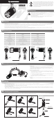
06 Assembly and Disassembly
In order to make the motor have longer service life and higher efficiency, we suggest to regularly check the bearing and clean the dirt in the motor. The specific time depends on the frequency of using the motor and
the site conditions. When installing, please follow the steps in the following assembly drawing; when disassembling, follow the reverse steps.
Parts List
04 Installation & Connection
1. Install the motor
The specifications of mounting hole screws are two sets of M4 and two sets of M3, and the mounting holes
are 5.5mm in depth, before installing the motor on the vehicle, please carefully confirm whether the
specification of the screws is appropriate according to the thickness of the motor mounting plate to avoid
damage to the motor due to too long screws.
2. How to Connect the Motor to an ESC
• When connecting the motor and esc, please pay attention to the marked three-phase position of A, B and
C to ensure that the three wires of the motor and esc are connected correspondingly. Otherwise, it cannot
run normally and even damage the esc and motor.
That is: Wire A of the esc matches wire A of the motor, wire B of the esc matches wire B of the motor,
wire C of the esc matches wire C of the motor.
• When the sensor wire of the motor is connected with the sensor wire of the esc, it shall be connected
correspondingly according to the arrow mark on the sensor interface.
3. Inspection
Before power on the esc, please check the reliability of the motor installation and the correctness of all
connections.
Back End Bell x 1Pcs
Screws for Fastening
the Back End Bell x 3pcs
(M2.5x4mm)
Screws for Fastening the Front
End Bell x 6Pcs (M2.5x5mm)
1. Mount the motor rotor
4. Mount the back end bell set
5. Mount screws for fastening
the back end bell
2. Mount the front end bell set
3. Mount screws for fastening
the front end bell
6. Picture of the assembled motor
1 2 3
4 5 6
Stator Set x 1Pcs
Front End Bell x 1pcs
Rotor x 1Pcs
Switch
Motor
Electronic Speed Controller
Motor B
Motor C
Motor A
68 ±0.3
5
4.5 Cut
14.5
18.5 ±0.5
4-M3 4-M4
25.40
22.5°
22.5°
C.C.W
R42
Dia. of cooling fins
3-
6.5 GBC
EZRUN 4278SD G2 EZRUN 4268SD G2