WELCOME TO THE HOBIE WAY OF LIFE Congratulations on the purchase of your new HOBIE 18’ and welcome to the HOBIE® sailing family. The HOBIE 18 cannot be outgrown. A single adult can sail it at top performance - and a crew of four can cruise in comfort. We offer this manual as a guide to increased safety and enjoyment of your new boat. The purpose of this publication is to provide easy, simple and accurate instructions on how to get your Hobie 18’ ready for the water.
HOBIE 18 ASSEMBLY MANUAL This assembly manual takes you stepby-step through the setting-up and sailing of your new HOBIE 18. This manual will help you understand each part in detail. Note that this manual applies for both Hobie 18 SE and SX models. Setting up your HOBIE 18 PAGE Packaging Layout.................................2 Framing the Hulls .................................3 Sailing your HOBIE 18 ................PAGE Installing the Trampoline ...................4-6 Balancing the boat ............
Packaging Layout Figure 1 1. 2. 3. 4. 5. 6. 7. 8. 9. 10. 11. 12. 13. 14. Port Hull Starboard Hull Back Bar Boom Tiller Cross Bar Front Bar Battens Rigkit Box #1 Rigkit Box # 2 Rudders Daggerboards Sail Main and Jib Trampoline Mast (not shown) Figure 2 See page 25 for descriptions Hobie Cat 18 SE Rig Kit Box #1 (fig 2) Description 1. 2. 3. 4. 5. 6. 7. 8. 9.
metal chips or dirt particles inside the bar which could be hindering the bolt's progress. *Port refers to left, starboard refers to right. Framing the Hulls (Recommend two people) Tools-HEX wrench (provided) and a screwdriver with a 1 /4" head. Retaining Channel Front Bar Inboard Bolt 3 3/4" Front Bar Outboard Bolt 2" Rear Cross Bar Inboard Bolt 2 1/ 2" Rear Cross Bar Outboard Bolt 2" Lock Nuts for 802-359 Outboard Bolts IMPORTANT Read this before framing the hulls.
Figure 6 10. The four outboard bolt assemblies are identical. To install, first slip the bolt through the outer end of the corner casting and down through the rail of the boat. Place the stainless steel channel over the bolt's exposed section which is under the rail. Spin the nylock nut on the bolt but do not tighten the bolt down at this time. TRAMPOLINE ASSEMBLY 11. Install all four outboard bolts in the manner described in step 10.
Figure 8 Figure 9 5
5. Insert the aft outboard corner of the trampoline into the extrusion on the inside of the hull and pull the trampoline as far aft as it will go. 6. Repeat steps 2-5 for installing the starboard trampoline. 7. In front of the rear cross bar there is a inboard rail. Insert the port aft lacing line on the port hull and exit it straight down. the tail of the line and then pull the knot rail. hole in either into this hole Tie a knot in up under the Figure 10 8.
MAST ASSEMBLY 1. Support mast at both ends on saw horses or other such devices. Ref: Illus. #1, Pg. 20. NOTE: The style of rotator yoke shown in Figure 12 is the older mast rotator style. Current models do not have a pulley. See page 20 for details on the new style. 2. Spreaders. In the rig kit you will find all the parts of the spreader assembly. 3. The larger of the two pairs of aluminum rods (1-1), is the spreader arm. Attach it to the aft tab of the spreader root (1-2).
19. Slip the port diamond wire into the tip of the port spreader arm. Make sure that the anti-chafing roller on the diamond wire is above the spreader tip. Secure the diamond wire by installing one of the long cotter pins (18) through the tip of the spreader. 25. Locate the shrouds and forestay in the rig kit. They are packed together and are the only rigging which is vinyl coated. The three wires are already attached to a large shackle.
STEPPING THE MAST. DANGER - Do not attempt to step the mast in an area of low overhead wires. A mast contacting an electrical wire could be fatal. 1. Secure the four trapeze wires near the bottom of the mast so that they will be out of the way while the mast is being raised. Jib Halyard Wire 2. Attach the jib halyard line to each end of the jib halyard wire to form a very large loop. Tie the line around the fork at the bottom of the forestay.
CAUTION: We recommend two people for stepping the mast. It is heavy for one person and could slip causing injury or damage. 8. Stand on the trampoline next to the back bar and raise the mast to your shoulders. Make sure the shrouds are not fouled and the stay adjusters are free before advancing further. Do not raise the mast in an area with any overhead wires. If everything is clear walk straight ahead raising the mast as you go. See Figures 20, 21, and 22. 9.
block on the end of the mast rotation control yoke and then feed it through the jam cleat. Tie a knot in the end of the line so that it will not slip back through the jam cleat. See Figure 35. 13. Lace it through the rope lock and then through the thimble at the end of the trapeze wire. Now tie the line onto either end of the dogbone. See Figure 23. 14. Repeat this process for the other three trapeze wires at the respective locations.
Hobie 18 and SX18 UPDATES INSTALLING THE SAIL BATTENS INSTALLING THE RUDDER ASSEMBLY The rudders were updated after 1987. The newer rudders use a black plastic cam to lock the rudder in the down position. Locate the left and right rudder assemblies. The left one has a red dot and the right one a green dot. The tiller arms should have a slight bow towards the centerline of the boat. Unfold the sail and lay it out on the trampoline. There will be a small bundle of thin lines tied to the top of the sail.
3. To distinguish the port rudder from the starboard rudder, the port rudder arm will bend toward the center of the boat when on the port hull. RUDDER AND TILLER CROSS BAR INSTALLATION (Pre 1987 boats) 1. Disengage the tiller arm from the lower casting and lock the tiller arm and rudder in the kicked up position. This will pull the rudder blade up and out of the way so the rudder pin can be installed. 4. Attach the tiller cross bar to the tiller arm as shown in figure 31. 2.
RAISING THE SAILS 1. Point the boat into the wind before you begin this operation. 2. Lay the main sail out on the trampoline. Insert the battens into the batten pockets starting at the top of the sail and working your way down. The batten has a tip on each end. The end without any holes goes into the sail first. Slip the batten in until it seats into the batten pocket protector at the leading edge of the sail. 3. Thread the batten tie through the aft batten tip and the sail as shown in Figure 33.
Figure 35 Note: Old style mast rotator shown here. 10. Attach the three boom blocks to the hangers on the boom. Secure the ratchet block to the top of the traveler car. Thread the mainsheet through the blocks as shown in Figure 37. Slip the other end of the mainsheet through the traveler jam cleat, then guide the line through the center of the traveler, and secure at the dead eye on the back bar. H18SX Downhaul Instructions 1. Using the twist shackle, attach the double block to the sail luff grommet. 2.
Raising the Jib 1. Attach the shackle on the end of the jib halyard wire to the head of the jib. 2. Wrap the luff pocket of the jib around the forestay and engage the zipper an inch or so. Next thread the jib halyard line inside the luff pocket. See Figure 38. Figure 39 9. Thread the remaining portion of the jib sheet through the starboard jib block in this same fashion. 10. The roller furler line can be temporarily secured in the jam cleat on the back side of the front cross bar.
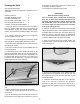
Figure 42 3. When raising or lowering the board do not rock it fore and aft. This will cause damage to the trailing edge. Pull the leading edge of the dagger board aft about 1/4 of an inch so that it is not contacting the lip of the deck and it can be easily moved up and down. DAGGER BOARDS 1. Slip the shock cord through the hole in the upper portion of the dagger board, take both ends to the hole on the out board deck flange. Pass both ends through the hold and tie a knot under the rail. 4. IMPORTANT.
HOBIE CAT 18 ’ 18
43 44 45 46 47 48 49 50 51 52 53 54 55 56 57 58 59 60 61 62 63 64 65 66 67 68 69 70 71 72 73 74 75 76 INDEX NO. DESCRIPTION 1 Arm 2 Brace 3 Slide 4 Diamond Wire (one side) 5 Gooseneck Yoke 6 Check Block 7 Mast Rotation Line 8 Modified Swivel Block 9 Shackle 10 Mast Rotation Assembly 11 Pin-Pawl Bearing, 5.5. 12 Ring-Halyard Line 13 Hook for Halyard Lock Assembly 14 Jib Furling Assembly 15 Bridle Wire Assembly 16 Screw - 5.5.
New Style Yoke Old Style Yoke Illustration No. 1 Mast Assembly 1-1 1-2 1-3 1-4 1-5 1-6 1-7 1-8 1-9 1-10 1-11 1-12 1-13 1-14 1-15 1-16 1-17 1-18 1-19 1-20 Spreader Arm Spreader Root Clevis Pin 3/16" x 11/16" Slide Clevis Pin 3/16" x 13/16" Brace Clevis Pin 3/16" x 9/16" Cotter Pin Mast Rotation Control Yoke Block Shackle Bolt 4-1/8" Lg.
Illustration No. 2 Jib Halyard Assembly 2-1 2-2 2-3 2-4 2-5 2-7 2-8 2-9 2-10 2-11 2-12 Jib Block Housing Jib Halyard Wire Luff Tensioner Jib Halyard Line Jib Block Sheave Clevis Pin A Cotter Pin Swedge Thimble Block Shackle Illustration No.
*Rudder system Pre-1987 shown Illustration No. 6 Rudder Assembly 6-1 6-2 6-3 6-4 6-5 6-6 6-7 6-8 6-9 6-10 6-11 6-12 6-13 6-14 6-15 Rudder Blade-Drilled Lower Rudder Casting Assembly Port Upper Rudder Housing Assembly Nut Nylock Bolt 2" Lg Spring Delrin Screw 1 / 4" I.D. Nyliner Rudder Cam Upper Rudder Housing Casting Rivet Locking Sleeve Pin Upper Rudder Housing Pin Lower Rudder Housing Tiller End Cap Illustration No.
Illustration No. 8 Traveler Assembly 8-1 8-2 8-3 8-4 8-5 8-6 8-7 8-8 8-9 8-10 1- 1/4" Lg H.H. Bolt Deck Plate Sheave Spacer Car Assembly Cotter Pin H.H. Nuts-Nylock Bearing Cylinder Pin-Clevis Bearing Ball Illustration No.
Illustration No. 10 (old style) Dolphin Post Assembly 10-1 Screw RHMS 10-2 Internal Lock Washer 10-3 Washer 10-4 Mast Step Pad 10-5 Bushing 10-6 Mast Step Casting 10-7 Dolphin Striker Post 10-8 Dolphin Striker Sleeve Illustration No.
Illustration No. 12 (new style) Tiller Connector 12-1 Tiller Connection Rod 12-2 Tiller Arm Swivel End Cap 12-3 Tiller Arm Insert 12-4 Bolt 12-5 Washer 12-6 Insert Bearing 12-7 Retainer Clip 12-8 Screw 17 Parts Relating to Diagram on Page 2 2 Rudder Pin 2 Cotter Pin for Rudder Pin 2 Jib Clew Block 1 Shackle 1 Gooseneck Vertex 1 Clevis Pin " 1 Split Ring 1 Gooseneck Bolt 1 Nut 11 Trapeze Seat Assy. 2 Trapeze Seat 2 Trapeze Hook 2 Trapeze Lacing Line 6' 12 Mast Rotation Control Yoke Assy.
Refer to the sail trim diagram below for approximate sail settings for the different points of sail or directions you will be sailing. Note the "can't sail zone". You cannot sail in this direction due to the fact that the sail will luff constantly when pointed into the wind. If you get stuck in irons (or stop pointed into the wind) you will need to reverse the rudder and push the sail forward to backwind it. The jib should be back winded by the crew to assist. This will back the boat up.
into deep enough water to lower the rudders. It is possible to launch in shallow water with the rudders partly up. Try not to steer with too much force on the rudders until you lock them in the down position. Keep the sail loose and trimmed out completely until you can power up and steer away from any obstacle. Trim the sail in quickly to get the boat moving forward and steer away from the wind slightly to prevent stalling into the wind.
stall the boat. Raise the rudders and drift back onto the beach. Always keep the boat pointed into the wind while beached and keep the sail trimmed out and uncleated. line while slowly leaning back away from the trampoline. Lean to approximately 45 degrees for best leverage. As the mast and sail lift out of the water and the upper hull begins to drop back into the water, drop down to your knees then into the water.
Continue to adjust and measure until you have the desired amount of forward rake. 4) If you wish to decrease the amount of forward rake turn the adjusting screw clockwise using a 3/16" Allen wrench. Check the decrease in the rake by the procedure in step 3 above . 5) Next, while holding the rudder forward against the lower casting, carefully latch the tiller arm down onto rudder housing. Loosen the adjusting screw on top of the tiller arm about 3/4 turn.
lamps. The wire coupling to the towing vehicle should be high enough to stay dry. Never rely on the trailer hitch for ground connection. Four-pole connectors should be used. A good anti-fouling paint can be applied for some protection from marine growth before mooring. Before painting, it is suggested that the area be masked off to ensure a clean line. No friction reducing paints or agents may be employed on a Hobie Cat during competition.
mast bend both ways. Also, the 18 has a controllable mast rotation device and an internal roller outhaul. Being as this boat does have a few more strings and lines on it than a 16, we designed and specially tooled a boom that carries internally your outhaul and mast rotation control, to try to keep the lines tucked inside as neatly as possible. All of the fittings on the boom are moveable; with the loosening of a screw you may slide any of the leads fore or aft as you find convenient.
Part # 63450001 CAUTION / SAFETY TIPS • Watch for overhead power lines. Never rig, trailer or sail the boat near overhead power lines. • Contact with a power line could be fatal. Install Drain Plugs. Even the most experienced of boaters forget to install the drain plugs sometimes. When installing the plugs, be sure that the threads and gaskets are free of sand/ grit. Any debris on • the plug could cause a water leakage. Sail to your experience. Do not try to do more than you can.