
Manual


2
2-3-0-745/ISS4/JULY13
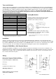
FIG. 4
Tones and Volumes
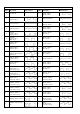
Table 1 below shows the full range of sound outputs available from the YBO-BSB and the amount of current drawn when
operated. When the YBO-BSB is selected to be a base sounder (sensor on top) the default sound output will be 85dB(A).
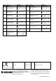
The YBO-BSB is also capable of utilising a number of different EN54-3 Approved tones. A total of 51 tones are available,
these are listed in Table 2 and in document AP092 available from our web site. The tone of the sounder and the
volume level is selected and controlled by the control panel, therefore check with the control panel manufacturer
for options and default values available.
Table 1
Locking Mechanism
The base sounder can be locked onto the relevant
mounting base by removing a plastic lug on the
underside of the sounder (see Fig. 3).
The sounder can then only be removed by using a
special Removal Tool (TSC-SRT), which is available
from Hochiki Europe (UK) Ltd.
Nominal Sound Output dB(A)*
1
*
2
Current Drawn mA*
3
50
0.8
55
0.8
60
0.8
70
0.8
78
1.5
80
2.0
85
3.0
88
4.5
90
6.5
93
8.0
94
10
95
11
98
16
*
1
@ 1m distance
*2 Refer to AP092 (available from our website) for complete EN54- A-
weighted sound levels
*
3
An additional 5mA will be drawn when beacon is activated
Installation
The base sounder is designed to be mounted on the Standard Mounting Base (YBN-R/3) or the Short-Circuit Isolator
Mounting Base (YBO-R/SCI, from batch code 6044 only) in the same method as a Sensor. The terminals on the mounting
base hold the YBO-BSB and in turn the terminals on the YBO-BSB hold the sensor, beacon or cap if being used as a wall
sounder (see below). For correct wiring of the appropriate mounting base, please refer to the diagram below.
Using the YBO-BSB as a Wall Sounder Beacon
A push-fit cap (SI/CAP) is available to cover the electrical connections if an analogue sensor, beacon or indicator is not
being fitted (see Fig. 2). Align the arrow marked inside the cap with the sensor alignment mark on the base sounder. This
will ensure the four tabs on the cover will engage with the matching slots in the base sounder. Push cap firmly onto the
base sounder until it clicks into place.
Wiring
Please refer to Fig. 4 for wiring the Standard
Mounting Base (YBN-R/3) and the Short-Circuit
Isolator Mounting Base (YBO-R/SCI):
A: Loop (+)
B: Loop (-)
C: Cable Screen (where used)
Operating Voltage: 17
NOTE: See AP0127 for short-circuit isolator
specifications for YBO-R/SCI
Fig. 3
Remove tab carefully using a pair
of pliers