
Install Instructions
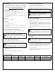


TYPICAL SEQUENCE OF OPERATION
1. When the float control “makes,” incoming electrical power
is supplied to the pump “ON-OFF” selector switch.
2. With the selector switch in the “ON” position the contactor
coil and the “Pump Run” pilot light will be energized.
3. When the contactor coil is energized, electrical power is
fed to the pump motor.
WIRING / CONNECTIONS
Wire incoming power to the terminals identified in the
Selection Chart on page 2.
Connect electrical ground wire to ground lug.
Wire the float switch.
Wire pump motor to the terminals identified in the
Selection Chart. Connect all necessary ground wires to the
ground lug. Connect ground lug to a good earth ground.
Check pump motor before installation for proper rotation.
Re-wire motor is necessary. Re-connect incoming power.
3
WARNING: HIGH VOLTAGE ELECTRICITY
Panel remains fully energized at all times, unless
incoming power is disconnected. Disconnect and lock out
power before connecting or servicing unit. Failure to follow
these instructions could result in serious injury or death.
ELEMENTARY DIAGRAM
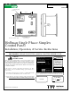
SINGLE PHASE SIMPLEX CONTROL PANEL