
Install Instructions
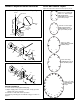

INLET
TEST
INLET
OUTLET
OUTLET
TEST
OUTLET
INLET
TEST
INLET
OUTLET
TEST
T
2
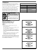
1. Determine where to install the trap, based on the
following requirements:
• The trap must be located as close as possible to, and
below the equipment to be drained.
• The trap must be in a straight run of horizontal pipe as
shown in the “Typical Piping Diagrams,” and pitched to
allow condensate to flow into trap inlet, and away from
trap outlet.
• Allow for enough space around the trap for servicing,
which may include removal of the body or cover,
depending on the model you are installing.
The Hoffman Series H traps provide an additional opening
where a test valve may be installed. On traps that do not
have an additional opening, the test valve can be installed
in a tee fitting in the discharge line.
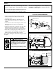
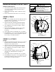
OPERATION
Float and thermostatic traps have two basic elements: a
thermostat for venting air from the system during start-up
and a float assembly for draining condensate.
The thermostat is normally open. It allows air to vent until it
is within 10-30°F (4-12°C) of the steam temperature.
The float assembly drains condensate from the system
when buoyancy force lifts the float ball and opens the
valve. The weight of the float ball causes the pin to close
against the trap seat when condensate is not present.
Materials of Construction
Part Specifications
Body and Cover Cast Iron 30,000 psi tensile
Valve Pin and Seat Stainless Steel (Hardened)
Float Stainless Steel
Lever Assembly Stainless Steel
Thermostatic Air Vent Stainless Steel Cage and
Thermal Element
Cover Bolts Grade 5
Baffle Stainless Steel {2
1
/2” units only}
To prevent serious personal injury from steam
pipe blow down, connect a temporary pipe
between the steam pipe opening and a drain,
or stand at least 100 ft. (30m) from the pipe
opening.
Failure to follow this warning could cause
property damage, personal injury, or death.
!
WARNING
INSTALLATION –
Series H, C and X Float and
Thermostatic Steam Traps
STEP 1