FITNESS SYSTEMS CL2061 March 2000 OWNERS MANUAL HOIST R Note: Both Serial Number and Model Number are Required when Ordering Parts RECORD SERIAL NUMBER HERE Customer Service (800) 548-5438 (619) 578-7676 Fax (619) 578-9558
A S S E M B LY I N S T R U C T I O N S CONTENTS INSTRUCTIONS (Step 1) 2 FRAME ASSEMBLY (Step 2) 4 PRE-ASSEMBLED PARTS (Step 3) 21 PARTS LISTING 23 HARDWARE LISTING 24 BOLT SIZING CHART 25 WASHER SIZING CHART 26 WEIGHT RATIOS 27 WEIGHT TRAINING TIPS 29 WEIGHT TRAINING EXERCISE LOG 31 DECAL REFERENCE 33 GENERAL MAINTENANCE 35 LIMITED WARRANTY 37 Page - 1 HOIST FITNESS SYSTEMS R 2061 Assembly
A S S E M B LY I N S T R U C T I O N S Step 1 INSTRUCTIONS Before beginning assembly please take the time to read the instructions thoroughly. Please use the catalog in this manual to make sure that all parts have been included in your shipment. When ordering use the part number and description from the catalog. Use only Hoist replacement parts when servicing. Failure to do so will void your warranty and could result in personal injury.
Page - 3 HOIST FITNESS SYSTEMS R 2061Assembly
A S S E M B LY I N S T R U C T I O N S Step 2 FRAME 2061Assembly ASSEMBLY HOIST FITNESS SYSTEMS R Page - 4
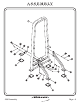
A S S E M B LY I N S T R U C T I O N S Step 2a FRAME ASSEMBLY In this step attach (2), (3), and (4) to (1). Wrench tighten bolts. Lift machine to position (5).
A S S E M B LY I N S T R U C T I O N S 1 A AA AB 4 AA AB AB AA A 5 5 AB AA A 3 AB AA 5 A 5 2 5 2061Assembly HOIST FITNESS SYSTEMS R Page - 6
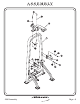
A S S E M B LY I N S T R U C T I O N S Step 2b FRAME ASSEMBLY Attach (6), (7), and (8) to (1). Wrench tighten bolts.
A S S E M B LY I N S T R U C T I O N S B AB AB 8 1 AB BA AB AA A 7 AB AA 6 A AB AB AA 2061Assembly A AA A HOIST FITNESS SYSTEMS R Page - 8
A S S E M B LY I N S T R U C T I O N S Step 2c FRAME ASSEMBLY In this step, start by pressing (CB) and (CA) into (12), insuring (CB) is pressed in the same side as (14) is mounted to (13). Place (9) over the two holes in the bottom of (1). Now slide (9) into the holes. Slide (11) and (12) onto (9). Make sure (12), (11), and (9) are sitting level, then fasten the top of each (9) to (1). Next attach (14) to (13). Secure (13) to (12), slide on (16) and attach another (14) to (1).
E 13 AH 2061Assembly HOIST FITNESS SYSTEMS Detail B 14 16 Detail A AG 14 AJ AK AD AK 11 9 10 12 CA F BB 15 9 10 CC AE 17 AF CB D AE AF AD AC C AD AC C See detail A for assembly instructions 1 See detail B for assembly instructions A S S E M B LY I N S T R U C T I O N S R Page - 10
A S S E M B LY I N S T R U C T I O N S Step 2d FRAME ASSEMBLY Continue assembling the CL2061 by sliding (19) into (18) and attaching (18) to (20). Next attach (21) to (20) and slide (20) on (23). Secure (23 to (8) and (1). Wrench tighten bolts.
A S S E M B LY I N S T R U C T I O N S F AD CE 24 19 AJ 20 G 8 AB CD AA 18 AD 21 AJ F 1 H 22 23 A AB AA 22 2061Assembly H HOIST FITNESS SYSTEMS R Page - 12
A S S E M B LY I N S T R U C T I O N S CABLE Step 2e INSTALLATION Part Descriptions Hardware Descriptions 26 - Hi-Lo Pulley Cable J - 3/8”-16 x 2” Button AC - 3/8” Split Washer AD - 3/8” Flat Washer CF - 3 1/2” Pulley CG - 4 1/2” Pulley CH - Snap Link Dia.
A S S E M B LY I N S T R U C T I O N S CG J AC AD AD AC AD AD AC CF AD J CG J AD AD J CG CG AD AC NOTE: CAUTION! Flange Nut must be in place to jam-lock pulley and keep it from twisting after proper cable tensioning has been performed. CH CG CG AC AD NOTE: CAUTION! Springs must be in place at cable ends or cable failure and risk of injury may occur.
A S S E M B LY M A N U A L Cable adjustments FINE TUNING Loosen jam nut and thread bolt in/out to give the cable proper tension. Re-tighten jam nut. Adjustments may need to be made during the first few session of use. Refer to the chart above for the points where adjustments to the cable tension may be made. The maintenance chart below should be followed to ensure that your equipment remains safe to use and continues to operate smoothly.
2061Assembly HOIST FITNESS SYSTEMS R Page - 16
A S S E M B LY I N S T R U C T I O N S Step 2f SHEILD ASSEMBLY Secure (25) to (1). Wrench tighten bolts.
A S S E M B LY I N S T R U C T I O N S 1 25 AB AA A AB AA A 2061Assembly HOIST FITNESS SYSTEMS R Page - 18
A S S E M B LY I N S T R U C T I O N S Step 2g FRAME ASSEMBLY Slide (27) up into (12) and secure with (CW). Part Descriptions Hardware Descriptions 12 - 8.6lb.
A S S E M B LY I N S T R U C T I O N S 12 CW 27 2061Assembly HOIST FITNESS SYSTEMS R Page - 20
A S S E M B LY I N S T R U C T I O N S Step 3 P R E -A S S E M B LY (Factory Installation) Insert (CT) into (1) and (23). Part Descriptions Hardware Descriptions 1 - Frame Assembly 6 - Handle Assembly, Right 7 - Handle Assembly, Left 8 - Top Pulley Mount Assembly 18 - Sliding Pulley Mount 20 - Pulley Mount 23 - Pulley Mount Adjuster Bar CJ - Radial Bearing CK - Adjuster Sleeve CL - Guide Rod Bushing CM - 2 x 4 End Cap (Horizontal H) CN - Rubber Grip (16.
8 2061Assembly HOIST FITNESS SYSTEMS 1 CN CR 6 20 CT CT FACTORY INSTALL 18 THREADED INSERTS (CT) TO WEIGHT CAGE (1) AND THE PULLEY MOUNT ADJUSTER (23) ROTATED FOR CLARITY CT CT CM CQ CL CT CP CK CV CT CT 1 CR CN CJ 7 CJ CQ 18 CT CT CS CS 23 A S S E M B LY I N S T R U C T I O N S R Page - 22
A S S E M B LY C A T A L O G PART LISTING Key # Qty Part Number Description 1 2 3 4 5 6 7 8 9 10 11 12 13 14 15 16 17 18 19 20 21 22 23 24 25 26 27 1 1 1 1 5 1 1 1 2 2 10 1 1 2 1 3 1 1 1 1 1 2 1 1 1 1 1 26-STD-SX655 26-STD-SX649 26-STD-SX648 26-STD-SX652 26-STD-PLAS195 26-STD-SX646 26-STD-SX647 26-STD-SX650 26-STD-SG143 26-STD-PLAS201 26-STD-SW104 26-STD-SWTOP12 26-STD-SX155 26-STD-SM295 26-STD-SX653 26-STD-SWADD7 26-STD-SM134 26-STD-SX651 26-STD-SM290 26-STD-SX645 26-STD-SX654 26-STD-PLAS221 26-STD-
A S S E M B LY C A T A L O G HARDWARE LISTING Key # Qty Part Number A B C D E F G H J 15 2 2 2 1 3 1 2 9 11-BTN-12112WZ 11-BTN-123WZ 11-BTN-38312WZ 11-BTN-5161 11-BTN-381 11-BTN-381WZ 11-HEX-125 11-FLA-121 11-BTN-382WZ 1/2"-13 x 1 1/2" BUTTON HEAD 1/2"-13 x 3" BUTTON HEAD 3/8"-16 x 3 1/2" BUTTON HEAD 5/16"-18 x 1" BUTTON HEAD 3/8"-16 x 1" BUTTON HEAD 3/8"-16 x 1" BUTTON HEAD 1/2"-13 x 5" HEX HEAD BOLT 1/2"-13 x 1" FLAT HEAD SCREW 3/8"-16 x 2" BUTTON HEAD AA AB AC AD AE AF AG AH AJ AK 16 20 12 22 2
OW N E R S M A N U A L WEIGHT RATIOS 1 2 3 4 5 6 7 8 9 10 11 100% 8.6 28.6 48.6 68.6 88.6 108.6 128.6 148.6 168.6 188.6 208.6 50% 4.3 14.3 24.3 34.3 44.3 54.3 64.3 74.3 84.3 94.3 104.3 50% The above chart shows the actual weight you are lifting when the ratios are applied. To find the actual weight you are lifting you would come down from the ratio being used and across from the number of the weight plate you have pinned.
2061 Assembly HOIST FITNESS SYSTEMS R Page 28
2061 Assembly HOIST FITNESS SYSTEMS R Page 30
OW N E R S Weight Training Exercise Log 2061 Assembly FITNESS SYSTEMS S=Sets R=Repetition per set W=Weight used Date Exercise S R W S R W S R W S R W S R W S R W S R W S R W S R W S R W S R W S R W Totals R HOIST Page 31 L A U N A M
2061 Assembly HOIST FITNESS SYSTEMS R Page - 32
Page - 33 A HOIST FITNESS SYSTEMS â Read and understand all instructions before using this equipment. â Inspect equipment for loose, worn or frayed parts. If in doubt about a certain part DO NOT use this machine. â Keep hands and feet away from moving parts. DO NOT attempt to free any jammed part by yourself.. â Always consult a physician before starting any exercise program. â Stop your workout immediately if you feel faint or dizzy.
2061 Assembly HOIST FITNESS SYSTEMS R Page - 34
OW N E R S M A N U A L HOIST FITNESS SYSTEMS GENERAL MAINTENANCE INFORMATION Links, Pull-Pins, Snap Locks, Swivels, Weight Stack Pins: F Check all pieces for signs of visible wear or damage. F Check springs in snap hooks and pull-pins for proper tension and alignment. F If the spring sticks or has lost its rigidity, replace it immediately. Upholstery: F To ensure prolonged upholstery life and proper hygiene, all upholstered pads should be wiped down with a damp cloth after every workout.
OW N E R S M A N U A L Continued: GENERAL MAINTENANCE INFORMATION Belt and Cable Tension: F Referring to the Assembly/Owners Manual, when belts or cables are used check all bolts and attachments to be sure they are properly attached. F Check slack in belts or cables and readjust tension if needed. Seat Sleeves & Oilites: F Wipe down adjusting tubes with a dust free rag before applying lubricant. F Lubricate seat sleeves and oilites with a Silicon or Teflon based lubricant spray.
OW N E R S M A N U A L Hoist Fitness Systems LIMITED LIFETIME WARRANTY Hoist Fitness Systems warrants this product to the original purchaser to be free from defects in workmanship and/or materials under normal use or service. If at any time a component part is defective, Hoist Fitness Systems shall repair or replace it (at Hoist Fitness Systems option) within a reasonable period of time. This warranty does not cover costs of removal, transportation or reinstallation.