OWNERS MANUAL HF4985 Note: Both Serial Number and Model Number are Required when Ordering Parts RECORD SERIAL NUMBER HERE CATALOG NUMBER 1205-000 Customer Service (800) 548-5438 (619) 578-7676 Fax (619) 578-9558
A S S E M B LY I N S T R U C T I O N S CONTENTS INSTRUCTIONS (Step 1) 2 FRAME ASSEMBLY (Step 2) 4 PRE-ASSEMBLED PARTS (Step 3) 17 PARTS LISTING 21 HARDWARE LISTING 22 WEIGHT TRAINING TIPS 23 WEIGHT TRAINING EXERCISE LOG 24 DECAL REFERENCE 25 MAINTENANCE SCHEDULE 28 GENERAL MAINTENANCE INFORMATION 29 LIMITED WARRANTY 31 Page - 1 HF4985 ASSEMBLY
A S S E M B LY I N S T R U C T I O N S Step 1 INSTRUCTIONS Before beginning assembly please take the time to read the instructions thoroughly. Please use the catalog in this manual to make sure that all parts have been included in your shipment. When ordering use the part number and description from the catalog. Use only Hoist replacement parts when servicing. Failure to do so will void your warranty and could result in personal injury.
A S S E M B LY I N S T R U C T I O N S Page - 3 HF4985 ASSEMBLY
A S S E M B LY I N S T R U C T I O N S Step 2 FRAME HF4985 ASSEMBLY ASSEMBLY Page - 4
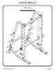
A S S E M B LY I N S T R U C T I O N S Step 2a FRAME Page - 5 ASSEMBLY Part Descriptions Hardware Descriptions 1 - Right Support Beam 2 - Left Support Beam 4 - Base Support 10 - Gusset Plate A - 1/2-13 UNC x 4” Hex Bolt AA - 1/2” Flat Washer BA - 1/2” Nylok Nut HF4985 ASSEMBLY
A S S E M B LY I N S T R U C T I O N S NOTE: Parts (1) and (2) are not the same. There are holes on the back side of the parts that are closer to one edge. That edge mounts to the inside of the unit (as shown in the diagram below). If mounted on the wrong side, the Safety Tier option will not work.
A S S E M B LY I N S T R U C T I O N S Step 2b FRAME ASSEMBLY Part Descriptions Hardware Descriptions 4 - Base Support 5 - Rear Support 6 - Rear Cross Member B - 1/2”-13UNC x 3 1/4” Hex Bolt AA - 1/2” Flat Washer BA- 1/2” Nylok Nut Page - 7 HF4985 ASSEMBLY
A S S E M B LY I N S T R U C T I O N S 5 B AA 6 AA B AA BA AA AA BA AA BA 5 4 AA BA 4 HF4985 ASSEMBLY Page - 8
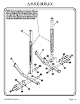
A S S E M B LY I N S T R U C T I O N S Step 2c FRAME Page - 9 ASSEMBLY Part Descriptions Hardware Descriptions 1 - Right Support Beam 2 - Left Support Beam 3 - Top Cross Member 5 - Rear Support 11 - Bar Rack A - 1/2”-13UNC x 4” Hex Bolt C - 1/2”-13UNC x 4 1/4” Hex Bolt AA - 1/2” Flat Washer BA - 1/2” Nylok Nut HF4985 ASSEMBLY
A S S E M B LY I N S T R U C T I O N S AA BA 3 AA BA C AA AA BA AA 5 A AA AA 5 AA BA 11 A AA C AA 1 AA 11 AA BA A AA 2 AA A HF4985 ASSEMBLY Page - 10
A S S E M B LY I N S T R U C T I O N S Step 2d FRAME ASSEMBLY In this step; first, slide (13) into (14) and secure to one side of (9), repeat for other side of (9) and Wrench Tighten bolts. Hook (9) onto both (11)’s. Next, place a finger of light grease (lithium, super lube, ect) into the inside of the bearings on both (8)’s. Using your finger, press the grease into the ball-bearings and their tracks. Repeat until the ball-bearing tracks are full of grease.
A S S E M B LY I N S T R U C T I O N S 14 AB 13 AB D BB Place a finger of light grease (lithium, super lube, ect.) into the inside of the bearing using your finger, press the grease into the ball-bearing and their tracks. Repeat until the ball-bearing tracks are full of grease. 12 Detail A Scale 2:1 12 Place a finger of light grease (lithium, super lube, ect.) into the inside of the bearing using your finger, press the grease into the ball-bearing and their tracks.
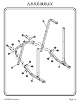
A S S E M B LY I N S T R U C T I O N S Step 2e FRAME ASSEMBLY Slide the top of (12) up into the hole on the bottom of (5). Next, slide the bottom of (12) into (7) and secure one (7) to (1), and the other (7) to (2). Wrench Tighten bolts.
A S S E M B LY I N S T R U C T I O N S 5 2 12 5 A AA 1 12 AA A AA BA 7 AA AA 7 BA AA HF4985 ASSEMBLY Page - 14
A S S E M B LY I N S T R U C T I O N S Step 2f FRAME ASSEMBLY Part Descriptions Hardware Descriptions 5 - Rear Support 15 - Weight Holder 16 - Rubber Donut E - 3/8”-13UNC x 1” Hex Bolt AB - 3/8” Flat Washer AC - 3/8” Lock Washer Page - 15 HF4985 ASSEMBLY
A S S E M B LY I N S T R U C T I O N S 5 Assemble the other 3 weight holders on this side as shown here. 16 5 AB 15 E Assemble the other 3 weight holders on this side as shown here.
A S S E M B LY I N S T R U C T I O N S Step 3a PRE-ASSEMBLY PARTS Part Descriptions 5 - Rear Support 18 - 2” x 3” End Cap Page - 17 HF4985 ASSEMBLY
A S S E M B LY I N S T R U C T I O N S 18 18 5 5 HF4985 ASSEMBLY Page - 18
A S S E M B LY I N S T R U C T I O N S Step 3b PRE-ASSEMBLY PARTS Part Descriptions Hardware Descriptions 7 - Guide Rod Support 8 - Olympic Weight Mount 9 - Olympic Weight Bar 15 - Weight Holder 16 - Rubber Donut 19 - 2” x 2” End Cap 20 - 1 5/8” Dia. End Cap 21 - Weight Horn Sleeve CA - Retaining Clip CB - 25mm Linear Bearing CC - 3/4” Flanged Oilite Bearing CD - 3/4” I.D.
A S S E M B LY I N S T R U C T I O N S 20 20 15 15 20 20 20 20 15 20 15 CA CB 20 19 8 19 16 21 7 CB 20 CC 7 CA CD 20 To be set in 5.88” deep 9 CD CA To be set in 5.
A S S E M B LY I N S T R U C T I O N S PART LISTING Key # Qty 1 2 3 4 5 6 7 8 9 10 11 12 13 14 15 16 18 19 20 21 1 1 1 2 2 1 2 2 1 2 2 2 2 2 8 10 2 2 18 2 Page - 21 Part Number Description 26-STD-HF985A-01 26-STD-HF985A-02 26-STD-HF985A-03 26-STD-HF985A-04 26-STD-HF985A-05 26-STD-HF985A-06 26-STD-HF985A-07 26-STD-HF985A-08 26-STD-HF985A-09 026-01P0453 026-01P0772 026-01G0155 026-01M0472 026-01M0473 026-01M0469 26-STD-06-0200 016-0101009 016-0101008 026-01PL183 26-STD-06-0201 Right Support Beam Left
A S S E M B LY I N S T R U C T I O N S HARDWARE LISTING Key # Qty Part Number Description A B C D E 16 4 4 2 8 011-0007013 011-0207011 011-0007015 011-0207022 011-0007083 1/2"-13UNC x 4" Hex Bolt 1/2"-13UNC x 3 1/4" Hex Bolt 1/2"-13UNC x 4 1/4" Hex Bolt 3/8"-16UNC x 2 1/4" Hex Bolt 3/8"-16UNC x 1" Hex Bolt AA AB AC 48 12 8 013-0002007 013-0202006 013-0006007 1/2" Flat Washer 3/8" Flat Washer 3/8" Lock Washer BA BB 24 2 012-0004001 012-0304004 1/2" Nylok Nut 3/8" Nylok Nut CA CB CC CD 4 4 2
OW N E R S M A N U A L WEIGHT TRAINING TIPS Always consult your physician before starting any exercise program. Hoist equipment is designed to maximize your time spent working out. Having an exercise routine planned out in advance will allow you to get the most benefit out of the time spent exercising, and will also enable you to work all the major muscle groups. Warm up properly before engaging in weight resistance training.
OW N E R S Weight Training Exercise Log S=Sets R=Repetition per set W=Weight used Date Exercise S R W S R W S R W S R W S R W S R W S R W S R W S R W S R W S R W S R W Totals Page - 24 HF4985 ASSEMBLY L A U N A M
A S S E M B LY I N S T R U C T I O N S DECAL Decal Descriptions P L AC E M E N T S 1 - 021-0003230 2 - SERIAL # DECAL 3 - 021-0003105-Y 4 - 021-0003104 1 2 4 3 Page - 25 HF4985 ASSEMBLY
HF4985 ASSEMBLY 8. CALL YOUR AUTHORIZED HOIST DISTRIBUTOR if you have any questions on the proper use or maintenance of this equipment. 7. CHILDREN SHOULD NOT BE ALLOWED TO USE THIS EQUIPMENT. To avoid possible injury, children should be kept at a safe distance when this equipment is in use. Teenagers should not use this equipment without adult supervision. 6. Take your time and do not rush the exercise. Practice proper breathing, NEVER hold your breath. 5.
A S S E M B LY M A N U A L DECAL REFERENCE These decals have been attached to this piece of equipment to provide information regarding operation, safety and maintenance. Before use, take the time to read these decals.
OW N E R S M A N U A L MAINTENANCE SCHEDULE ROUTINE COMMERCIAL MAINTENANCE HOME MAINTENANCE Inspect; Links, Pull Pins, Snap Locks, Swivels, Weight Stack Pins DAILY WEEKLY Clean; Upholstery DAILY WEEKLY Inspect; Cables or Belts and their tension DAILY WEEKLY Inspect; Accessory Bars and Handles WEEKLY 3 MONTHS Inspect; All Decals WEEKLY 3 MONTHS Inspect; All Nuts and Bolts, Tighten if Needed WEEKLY 3 MONTHS Inspect; Anti-Skid Surfaces WEEKLY 3 MONTHS Clean & Lubricate; Guide Rods
OW N E R S M A N U A L HOIST FITNESS SYSTEMS GENERAL MAINTENANCE INFORMATION Links, Pull-Pins, Snap Locks, Swivels, Weight Stack Pins: F Check all pieces for signs of visible wear or damage. F Check springs in snap hooks and pull-pins for proper tension and alignment. F If the spring sticks or has lost its rigidity, replace it immediately. Upholstery: F To ensure prolonged upholstery life and proper hygiene, all upholstered pads should be wiped down with a damp cloth after every workout.
OW N E R S M A N U A L Continued: GENERAL MAINTENANCE INFORMATION Cable Tension: F Referring to the Assembly/Owners Manual, check all cable bolts and attachments to be sure they are properly attached. F Check slack in cables and readjust cable tension if needed. Seat Sleeves, Turcite Bushings: F Wipe down adjusting tubes with a dust free rag before applying lubricant. F Lubricate seat sleeves and turcite bushings with a silicon or Teflon based lubricant spray.
OWNER'S MANUAL HOIST FITNESS SYSTEMS LIMITED LIFETIME WARRANTY Hoist Fitness Systems warrants this product to the original purchaser to be free from defects in workmanship and/or materials under normal use or service. If at any time a component part is defective, Hoist Fitness Systems shall repair or replace it (at Hoist Fitness Systems option) within a reasonable period of time. This warranty does not cover costs of removal, transportation or reinstallation.