
User's Manual
5 of 10
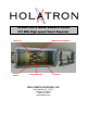
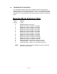
The user has access to the following components (refer to annotated cover photo):
1.1 THE ANTENNA.
The RF signal is received and retransmitted by a single quarter-wave screw-on
antenna. The circuit board acts as a ground plane for this antenna. Both are
contained within the repeater enclosure and will operate with undiminished range
even when the lid is closed. Note that range is optimized when the receiver is
elevated at least 12” above nearby conductive objects such as car hoods, metal
bleachers, or earth ground, and the antenna is vertical. When installing the
antenna, it should only be hand-tightened to the point where mechanical
resistance begins to be felt. That is all that is required for good electrical contact.
Excessive tightening can damage the antenna jack to the internal circuit board.
The antenna should never be tightened with pliers or any similar tool.
1.2 THE POWER SWITCH.
This miniature toggle switch, located on the top side of the internal circuit board,
turns on power to the receiver. When finished, don’t forget to turn it off in order
to conserve battery life. There is no external indicator to show that it is on.
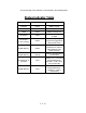
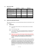
1.3 THE STATUS INDICATOR.
While the power switch is on, this indicator, located on the top side of the internal
circuit board, will flash intermittently in bursts of one, two, or three green flashes
at a time if the battery voltage is high enough to reliably power the repeater.
The bursts indicate the amount of energy remaining in the batteries. If no
flashing occurs, the batteries must be replaced before the transmitter can be
used reliably. Three flashes per burst indicate that the batteries have full
capacity, two flashes indicate that their capacity is beginning to diminish, and
one flash indicates that they are near the end of their useful lifetime in which
case they should be replaced immediately after the current use. Adequate
repeater output to achieve the specified range will occur as long as the total
series battery voltage is above approximately 5 volts, but the battery voltages will
drop rapidly at this point
This indicator will also light green while a signal is being received that matches
the expected Holatron preamble and sync code of the system communication
protocol, even if it is from a transmitter operating on digital channel that is
different from the one selected with the mode selector switch.
When repeater mode is selected (switch positions 0 – D), this indicator will light
up orange while retransmission is occurring. In continuous transmission
(broadcast) mode (switch positions E or F), it will light up red as each data
packet is transmitted.