
User's Manual

7 of 10
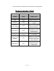
1.4 THE MODE SELECTOR SWITCH.
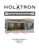
This 16 position miniature rotary switch, located on top of the internal circuit
board as shown in the cover photo, is used to select one of 16 possible repeater
operating modes. It can be set to positions 0 – 9 or A – F by rotation with a small
screwdriver. The mode selected by each switch position is shown in the following
table:
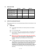
Repeater Mode Selection Table
Switch Repeater
Position Mode
----------- ------------
0 Repeat all Holatron commands.
1 Repeat only channel 1 Holatron commands.
2 Repeat only channel 2 Holatron commands.
3 Repeat only channel 3 Holatron commands.
4 Repeat only channel 4 Holatron commands.
5 Repeat only channel 5 Holatron commands.
6 Repeat only channel 6 Holatron commands.
7 Repeat only channel 7 Holatron commands.
8 Repeat only channel 8 Holatron commands.
9 Repeat only channel 9 Holatron commands.
A Repeat only channel 10 Holatron commands.
B Repeat only channel 11 Holatron commands.
C Repeat only channel 12 Holatron commands.
D Repeat all Holatron commands on channel 1, code 0.
E Transmit channel 1, code 0, cue 1 command at 0.5 Hz.
F Transmit channel 12, code 0, cue 1 command at 6.22 Hz.
NOTE: Positions “E” and “F” have been disabled in order to comply with
FCC and IC requirements.