
Installation Guide

Page 4
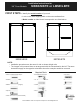
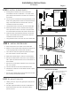
STEP 3 - HEADER BLOCK HEIGHT CALCULATION:
a. Measure height of glass panels: __________
b. Subtract 4 9/16” from this measurement: _________
c. This is the height from the threshold to the bottom of the
Header Block in the following step.
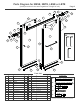
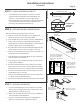
STEP 1 - EVALUATE THRESHOLD
Mark
Centerline
up walls
and along
threshold
Installation Instructions
All Models
Illustration #1Illustration #3
a. With a level, determine the vertical threshold outage as shown
in Illustration 1. Maximum recommended vertical threshold
outage from side to side is ¼”.
b. Mark high side and low side of threshold. The first header block
will be installed on the high side.
STEP 2 - CENTERLINE
a. Mark the location of the center of the threshold.
b. Draw overall unit centerline on threshold and walls. A laser or
plumb-bob is handy to determine and mark the centerline.
c. Place the Center Guide at the threshold center location. On the
threshold, mark the position of a long edge of the Center Guide
perpendicular to the unit centerline. Remove the Center Guide.
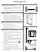
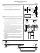
STEP 4 - MOUNT FIRST HEADER BLOCK
a. Lean the inner glass panel against the inside back wall of the
shower. Be sure to place cardboard or a soft material between
the glass and the floor.
b. Use measurement from STEP 3 and mark this distance up the
high-side wall along the centerline. This is the location of the
BOTTOM of the Header Block.
c. Insert two 7mm Stoppers and two 30mm Stoppers through the
holes in the backside of each Header Block. See Illustration 3
for Stopper orientation. All bumpers should be flush to back of
the Header Block.
NOTE: Refer to the “Proper Backing” bullet on page 2.
d. Place the bottom of the Header Block at this mark and center
along the centerline.
e. Mark the 3 Header Block hole locations on the wall.
f. Remove the Header Block and drill a hole at each mark with a
¼” drill bit. Insert a M5 Wall Anchor into each hole.
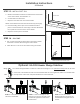
g. Secure the Header Block with two M5 X 60mm FHPH Screws in
the outer hole locations and one M5 X 60 THPH Screw in the
center hole location.
Mark Hole Locations
For 3 Screws
STEP 3 Calculation
7mm
Stoppers
30mm
Stoppers
7mm
Stoppers
30mm
Stoppers
Header Block
Top View
7mm Stoppers are inserted into the
Header Block and should be
oriented so that they receive the Inside
Panel at the showerhead wall.
(Reverse for opposite wall)
Showerhead
Threshold
High Side Low Side
Illustration #2
M5 X 60mm Flat Head Screws
(ITEM #3a)
M5 X 60mm
Truss Head
Screw
(ITEM #3b)