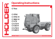
Operating Instructions C-Trac C 9700 C 9700 H C 9800 H C 9.72 C 9.72 H C 9.83 H C 9.78 H C 9.88 H Order No.: 145 052 Date of Issue: 23.10.
C 9700 ... C 9.88 H Operating Instructions Foreword We congratulate you for having chosen a product from HOLDER. We would like you to be able to work safely with your tractor and without malfunctions, and therefore we recommend you follow the instructions in this operating manual. You also ensure getting full value from your tractor, save yourself trouble and maintain your warranty. The operating manual provides you with the required information.
Operating Instructions C 9700 ... C 9.88 H Foreword In case of questions regarding your tractor, please state the following data: Tractor Model ................................................ eg C 9800 H Engine Serial Number .................................. eg 00542087 Chassis Serial Number ................................. eg 52410101 Date of Sale, or Date of Complaint ............. eg 02.01.2003 Operating Hours .............................
C 9700 ... C 9.88 H Operating Instructions Foreword Table of Contents Chapter Page Chapter Page Foreword ........................................................................ 1 Maintenance Schedule ................................................ 157 Instructions for the Tractor ............................................ 5 Maintenance during the First Period of Operation ....... 161 Instructions for Operation .............................................. 7 Maintenance as Required ..........
C 9700 ... C 9.88 H Operating Instructions Instructions for the Tractor After the safety test, this tractor has received the operating permit acc. to 74/150/EEC. The tractor conforms to the EMC (Electromagnetic Compatibility) requirements of directive 89/ 336/EEC. The regulations for exhaust gas identification and the noise emissions are observed. The tractor must be registered and the license plate must be attached at the front and/or rear if applicable.
Operating Instructions C 9700 ... C 9.88 H Instructions for the Tractor Residual Hazards and Risks Despite all care being taken and in conformance with standards and regulations, it is not possible to exclude all risks in the handling of the tractor. The tractor and all other system components conform to currently applicable safety regulations. Nevertheless, a residual risk cannot be excluded even by authorized use of the tractor and observation of all the safety notices given.
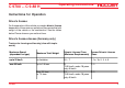
C 9700 ... C 9.88 H Operating Instructions Instructions for Operation Driver's license For the operation of this vehicle you need a driver's license dependent of the maximum speed and the permissible total weight of the vehicle or the combination. See the tables below. Please observe your national laws.
Operating Instructions C 9700 ... C 9.88 H Instructions for Operation Single-axle Trailers or Two-axle Trailers with an Axle Base of up to max. 1 m up to 750 kg trailer weight Driver's License Class (Minimum Requirements) B, C1, C, T Former Driver's License Class 1, 1a, 1b, 2, 3, 4, 5 over 750 kg trailer weight L: 25 only with additional sign and maximum tractor speed of 25 km/h (depending on type) BE, C1E, CE, T 1, 1a, 1b, 2, 3, 4, 5 Maximum Total Weight B, C1, C: only up to 3.5 tons adm.
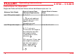
Operating Instructions C 9700 ... C 9.88 H Instructions for Operation Multiple-axle Trailers and Two-axle Trailers with an Axle Base over 1 m up to 750 kg trailer weight Driver's License Class (Minimum Requirements) B, C1, C, T Former Driver's License Class 2, 3 over 750 kg trailer weight L: 25 only with additional sign and maximum tractor speed of 25 km/h (depending on type) BE, C1E, CE, T 2, 3 Maximum Total Weight up to 3.5 tons Maximum Total Weight B, C1, C: only up to 3.5 tons adm.
Operating Instructions C 9700 ... C 9.88 H Instructions for Operation Two Trailers behind Tractors for Farming and Forestry Maximum Total Weight up to 3.5 Maximum Total Weight up to 12 Maximum Total Weight Driver's License Class (Minimum Requirements) BE, C1E, CE, T Former Driver's License Class 2, 3 B, C1, C in each case only up to 3.5 tons adm. total weight of the combination and adm. total weight of trailers ≤ dead weight of tractor; otherwise: 25 1, 1a, 1b, 4, 5, C1E: only up to 12 tons adm.
C 9700 ... C 9.88 H Operating Instructions Instructions for Operation Safety Working Clothes • General Notes on Safety • • • • • • • • • Observe the VSG 3.1 (German regulations for safety and health protection). Do not allow children under 16 to use the tractor. When using the public highway, respect the highway code. Do not allow anyone to stand around where they might get hurt. Do not run the engine in enclosed spaces. Exercise extreme caution when handling fuels - there is a high risk of fire.
Operating Instructions C 9700 ... C 9.88 H Instructions for Operation • • - - The installed equipment must conform to the applicable EMC directive 89/336/EU and carry the CE symbol. If you must install a mobile communications system (or have it installed) (eg radio, mobile telephone), the following requirements must be met: Only approved equipment (eg BTZ approval in Germany) may be installed. The equipment must be installed permanently.
C 9700 ... C 9.88 H Operating Instructions Instructions for Operation let them come in contact with hot engine parts as fire can result. Battery Acid Battery acid contains dissolved sulphuric acid. This acid is poisonous and caustic. When working with battery acid, always wear protective clothing and eye protectors. Do not allow acid to contact clothing, skin or eyes. In case of contact, wash directly with ample clean water. If personal injuries exist, seek medical aid at once.
Operating Instructions C 9700 ... C 9.88 H Instructions for Operation particles in the exhaust gases can cause cancer. For this reason the engine may not be operated in enclosed spaces. Heat The exhaust gases are very hot and can ignite inflammable material. The exhaust gas pipe should therefore be kept away from ignitable material. Battery During charging, the battery produces a mixture of oxygen and hydrocarbon (detonating gas). This mixture of gases is explosive and may not be ignited.
C 9700 ... C 9.88 H Operating Instructions Technical Data Model Variants Model Transmission Type of Drive Type of Engine Engine Performance C 9700 Mechanical Reversing Gearbox Mechanical BF4M1011 53.5 kW ^ = 72 HP (DIN) C 9700 H Hydrostatic transmission Hydrostatic BF4M1011 53.5 kW ^ = 72 HP (DIN) C 9800 H Hydrostatic transmission DUAL DRIVE* BF4M1011F 61 kW C 9.72 Mechanical Reversing Gearbox Mechanical BF4M1011 53.5 kW ^ = 72 HP (DIN) C 9.
Operating Instructions C 9700 ... C 9.
Operating Instructions C 9700 ... C 9.88 H Technical data Table of Dimensions Trailer Coupling Tires Type Overall Height Avg. Height of Seat Ground Clearance Lowest Position Highest Position Height of Body a mm (Inches) b mm (Inches) c mm (Inches) d mm (Inches) d mm (Inches) g mm (Inches) 10.5-18 MPT S 524-31-6 2130 (83.8) 1050 (41.3) 230 (9) 575 (22.4) 975 (38.2) 1130 (44.5) 10.5-18 MPT 524-31-1 2130 (83.8) 1050 (41.3) 230 (9) 575 (22.4) 975 (38.2) 1130 (44.5) 36x13.
Operating Instructions C 9700 ... C 9.88 H Technical data Track Widths Tires Min. Turning Radius to DIN 7020 (measured at outermost point of vehicle) m 7.28 m f. track w. 1084 7.10 m 10.5-18 MPT S f. track w. 960 7.14 m 10.5-18 MPT f. track w. 1034 7.30 m 400/60-15.5 f. track w. 1070 7.15 m 33x12.50 R15 f. track w. 1000 7.15 m 33x12.50-15 f. track w. 1000 7.24 m 33x15.50-15 f. track w. 1124 7.45 m 33/18LL-16.1 f. track w. 1164 7.30 m 31x15.50-15 f. track w. 1124 *Snow chains not possible 36x13.
Operating Instructions C 9700 ... C 9.88 H Technical data Weights All Tractors Accessories Total Front Rear Creep speed gear 13 kg (28.6 LBS) 10 kg (22 LBS) 3 kg (6.6 LBS) (5864 LBS - 5952 LBS) Rear lift *2660 kg - 2700 kg (5864 LBS - 5952 LBS) 77 kg (169.7 LBS) -25 kg (-55 LBS) 102 kg (224.8 LBS) Loading platform 75 kg (165.3 LBS) 0kg (0 LBS) 75 kg (165.3 LBS) Weight in kg 4500 kg (9920.
Operating Instructions C 9700 ... C 9.88 H Technical data Tires Type of Tire Ply Profile Tube Inflation Pressure Wheel Weights Type Weight 10.5-18 MPT S 6 Cleat profile yes 1.5 bar (22 PSI) 524-34-1 approx. 45 kg (100 LBS) 10.5-18 MPT 6 Cleat profile yes 1.5 bar (22 PSI) 524-34-1 approx. 45 kg (100 LBS) 31x15.50-15 8 Profile no 2.0 bar (14-29 PSI) 524-34-1 approx. 45 kg (100 LBS) 33x15.50-15 4 Profile no 1.0 bar (14.7 PSI) 524-34-1 approx. 45 kg (100 LBS) 33x12.
Operating Instructions C 9700 ... C 9.88 H Technical data Engine Specifications C 9700/9.72 C 9700/9.72H C 9800/9.73H C 9.78H C 9.
Operating Instructions C 9700 ... C 9.88 H Technical data Theoretical Driving Speeds Transmission Unit Gearbox Hydrostatic Drive Hydrostatic Drive Hydrostatic Drive Dual Drive Dual Drive Dual Drive Engine Output kW 53.5 53.5 57 61 65 53.5 57 61 65 Engine speed rpm 2500 2500 2600 2800 2500 2600 2800 Tires Type 36x13.50-15 524-31-8 km/h 36.8 30.8 32.0 34.4 38.4 39.9 43.0 10.5-18 MPT 524-31-1/-6 km/h 35.9 30.1 31.3 33.7 37.6 39.1 42.1 400/60-15.
C 9700 ... C 9.88 H Operating Instructions Technical data Technical Data/Filling Quantities Assembly Suppl.
Operating Instructions C 9700 ... C 9.88 H Technical data Assembly Suppl.
Operating Instructions C 9700 ... C 9.88 H Technical data Assembly Suppl. Information Description Rear lift - Model HOLDER 3-point standard - Mounting Category I and II - Lifting power 15700 N (at installation points) - Cylinders 2 double-acting cylinders Drive Hydraulics Variable pump Hydromatik - Model A11 VG 50 EP / A4 VG 40 EP - Flow rate 160 l/min (42 GAL/MIN) - Operating pressure 300 bar (4410) (max. 350 bar (5145)) / 380 bar (5586) (max.
Operating Instructions C 9700 ... C 9.88 H Technical data Assembly Suppl. Information Description Hydraulics for implements (with steering) Pump Sundstrand - Make - - Flow rate 17 cm3/rev (42.5 l/min at 2500 engine rpm) - Operating pressure 180 -190 bar Hydraulic oil tank 22 l (5.8 GAL.) Electrical System - Operating voltage 12 VDC - Battery 12 V / 88 Ah - A/C alternator 14 V / 60 A - Starter 12 V / 2.
Operating Instructions C 9700 ... C 9.88 H Technical data Noise Level The tractor emits the following noise level (measured at the driver's ear) according to EU Standard 77/311/EEC; measurement according to Appendix II. Table of Noise Levels and Absorption Rating Model Engine Type Engine Output Noise Level dB(A) Cabin open* Absorption rating Cabin closed C 9700 BF4M1011 53.5 kW (72 HP) 79 78 2.1 C 9700 H BF4M1011 53.5 kW (72 HP) 79 78 2.1 C 9800 H BF4M1011F 61 kW (83 HP) 79 78 2.
Operating Instructions Description 2 1 C 9700 ... C 9.
Operating Instructions C 9700 ... C 9.
Operating Instructions C 9700 ... C 9.
Operating Instructions C 9700 ... C 9.
Operating Instructions C 9700 ... C 9.
C 9700 ... C 9.88 H Operating Instructions Description Multi-function Lever 1 NOTE Various types of multi-function levers can be installed.
Operating Instructions C 9700 ... C 9.
C 9700 ... C 9.
Operating Instructions C 9700 ... C 9.
C 9700 ... C 9.
Operating Instructions C 9700 ... C 9.
Operating Instructions C 9700 ... C 9.
Operating Instructions C 9700 ... C 9.
C 9700 ... C 9.
Operating Instructions C 9700 ... C 9.
Operating Instructions C 9700 ... C 9.
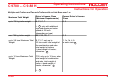
Operating Instructions C 9700 ... C 9.88 H Description Mounting Instructions for License Plate - Install the front license plate (1) above the upper link support at the front cabin wall. - Install the rear license plate (2) at the rear below the left tail light.
C 9700 ... C 9.88 H Operating Instructions Description Overview of Options and Variants Assembly Suppl. Information Dimension /Order No.
Operating Instructions C 9700 ... C 9.88 H Description Assembly Suppl. Information Dimension /Order No./Type Power hydraulics 75 l/min fixed displacement 524-80-35 - Pump Mounted on drive pump Gear pump - Delivery capacity 22 cm³/rev - Flow rate 75 l/min - Maximum pressure 210 bar Flow divider I. Circuit 524-80-25 - Pump Standard pump - Delivery capacity 17 cm³/rev - Flow rate 0-25 l/min - Maximum pressure 200 bar Flow divider II.
C 9700 ... C 9.88 H Operating Instructions Description Assembly Suppl. Information Dimension /Order No.
Operating Instructions C 9700 ... C 9.
C 9700 ... C 9.88 H Operating Instructions Taking into Service 1 2 Daily Checks and Activities before Taking into Service If damages or defects are found during the following checks, they must be eliminated before taking the vehicle into service. Do not operate the tractor before proper repairs are carried out. Safety and protective devices should not be removed or disabled. Fixed specified settings may not be changed.
Operating Instructions C 9700 ... C 9.88 H Taking into Service Turning on the Battery Isolating Switch 1 NOTE The battery can be switched off completely with the removable key. - Insert the key (1) in the battery isolating switch and set it to the vertical position. The battery circuit is turned on. Checking Engine Oil Level NOTE Check the engine oil level only when the tractor is on level ground. - Let the engine run approx. 2 minutes with the heat shut-off valve open.
C 9700 ... C 9.88 H Operating Instructions Taking into Service Checking the Trailer Hitch (Optional), if required - Check the trailer hitch for proper condition and working. Carry out the check according to the instructions in the section "Operating the Trailer Hitch". Checking Tire Inflation Pressure NOTE Your tractor can be equipped with different types of tires. The specified inflation pressure for your tires is given in the table entitled "Tires" in the technical data section.
Operating Instructions C 9700 ... C 9.88 H Taking into Service Checking the Drive Hydraulics Oil Level - 1 Withdraw the oil dipstick (1). The oil level must be at the marking (2). Top up oil as specified in the maintenance manual. 2 Bild_026 Checking the Implement Hydraulics Oil Level - - 1 2 Retract all hydraulic cylinders. Check the oil level at the sight glass (2). The oil level must be at the centre (1) of the sight glass. Top up oil as specified in the maintenance manual.
C 9700 ... C 9.88 H Operating Instructions Taking into Service Filling Fuel - 1 If necessary, read the fuel level (1) on the multifunction display. CAUTION Danger of fire when handling fuels. Turn off the engine. Do not fill any fuels in the vicinity of naked flames, ignition sparks or hot engine parts. Do not smoke during refuelling. - Remove the fuel tank filler cap (2). Top up Diesel fuel as specified in the maintenance manual. Filling quantities ............ approx. 86 litres (22.7 USGAL.
Operating Instructions C 9700 ... C 9.88 H Taking into Service Checking the Brake Fluid Level - 1 2 Check the brake fluid level at the brake fluid reservoir (2). The brake fluid level must be between the Min and Max marking at the reservoir. Top up the brake fluid as specified in the maintenance manual. Adjusting the Steering Wheel NOTE The tilt of the steering wheel can be set to a comfortable position. 4 3 DANGER Do not adjust the steering wheel while driving. - Loosen the star knob (3).
C 9700 ... C 9.88 H Operating Instructions Taking into Service Adjusting the Driver's Seat 1 2 3 4 5 6 2 1 Backrest Adjustment knob for lumbar padding Backrest adjustment Weight adjustment Horizontal cushioning Horizontal adjustment DANGER Do not adjust the seat while driving. Risk of accidents! - Adjust the seat so that all controls can be reached and operated safely. Bild_010 6 5 4 3 NOTE Observe the operating manual for the seat supplied with your tractor.
Operating Instructions C 9700 ... C 9.88 H Taking into Service Adjusting the Driver's Weight - 2 1 Sit down on the driver's seat. Pull the weight adjustment handle (4) up. NOTE An alert sounds. The seat is automatically set to the weight of the driver; The alert ceases. - Release the lever. Adjusting the Horizontal Suspension - - Push the horizontal suspension lever (5) back: the seat suspension is unlocked in horizontal direction.
C 9700 ... C 9.88 H Operating Instructions Taking into Service Adjusting the Passenger Seat 1 2 3 4 1 Backrest Weight adjustment Horizontal adjustment lever Backrest tilt adjustment Adjusting the Weight - Sit down on the seat. - Press the weight adjustment knob (2) from the top down until the weight is reached on the scale; The weight can be adjusted in 9 stages of 50 to 130 kg. - Release the knob when your weight is indicated. NOTE Only push the knob from the top down.
Operating Instructions C 9700 ... C 9.88 H Taking into Service Filling Washing Water 1 NOTE The washing water reservoir for the windshield washer is located beneath the passenger seat. - Tilt the seat forward. Open the filler cap (1) and add washing water into the reservoir (2). Filling capacity ............ approx. 2.5 litres (0.66 USGAL.) 2 Checking the Lights and Rear View Mirror - - Check that the lighting is functioning properly.
C 9700 ... C 9.88 H Operating Instructions Taking into Service Starting the Engine Instructions before Starting the Engine DANGER Do not start or run the engine in enclosed spaces. Danger of poisoning through exhaust gases! Instructions before Starting CAUTION Before starting, check to ensure no one is in the vicinity of the tractor. ATTENTION Do not use a starting aid such as Startpilot or similar means. Turn off the drive or driven attaching implements.
Operating Instructions C 9700 ... C 9.88 H Taking into Service Starting the Engine - 1 1 Shift the gearshift lever (gearbox) to neutral. Set the forward/reverse selector lever (1) to the neutral position (centre). Depress the clutch pedal (gearbox) or inch pedal (hydrostatic drive). NOTE The engine can only be started if the pedal is fully depressed (starting safety switch). Bild_180 - Set the hand throttle (2) to idle (push in fully).
C 9700 ... C 9.88 H Operating Instructions Taking into Service NOTE The battery charge indicator (8), engine oil pressure indicator (7), parking brake indicator(6) (if parking brake is engaged) and the red indicator for km/h or x10 (3) in the multifunction display come on. - Turn the ignition key to position 2 to preheat the engine. The preheating indicator (4) comes on. NOTE When starting at low temperatures, hold the ignition key longer (approx. 1 minute) in position 2.
Operating Instructions C 9700 ... C 9.88 H Taking into Service - Release the ignition key as soon as the engine turns over. The battery charge indicator (8) and the engine oil pressure indicator (7) will go out. Set the engine speed with the hand throttle (1) or accelerator pedal to the desired RPM (5) . 3 8 7 6 4 5 Bild_033 Checking the Brakes and Steering for Proper Operation - Make a short trial run and check the steering and brakes for proper operation.
C 9700 ... C 9.88 H Operating Instructions Operation Before Starting to Drive When driving on public highways, observe the regulations of the highway code. • Driving Safety Rules • • • • • Drive the tractor only from the driver's station with the cab doors closed. Always adjust your speed to the driving conditions and the load you are carrying. Never drive downhill without having the tractor in gear or with the engine stopped.
Operating Instructions C 9700 ... C 9.88 H Operation Driving 1 Driving with Hydrostatic Drive and Digital Electronics - Start the engine. - Select the direction of travel with the forward/reverse selector lever (3) (forward left or reverse right). - The direction arrow for forward (1) or reverse (2) travel comes on. NOTE After starting the engine, the forward/reverse selector lever must be operated once if it was in the forward or reverse position when starting.
Operating Instructions C 9700 ... C 9.88 H Operation Table of Driving Ranges Position - Symbol Function Travel Speed* Use 0 - 30 / 36 km/h Low tractive force, eg for highway driving Top position S Fast speed Centre position 0 Drive off Bottom position L Slow speed Select the desired driving program at the driving program switch (6). The selected position is illuminated: Towing 0 - 11.
Operating Instructions C 9700 ... C 9.
C 9700 ... C 9.88 H Operating Instructions Operation Selecting Road Speed (Transport Speed) 5 The tractor is stationary. - Set the program switch (6) to range 1 or 2. NOTE The driving range can also be switched while driving at reduced ground speed. - - Disengage the parking brake. Depress the accelerator pedal for the desired ground speed. The tractor starts driving and can be driven up to maximum ground speed of the selected range.
Operating Instructions C 9700 ... C 9.88 H Operation The tractor is stationary. - Set the inch knob (5) to 0. - Set the program switch (6) to range 3 or 4. - Adjust the PTO rpm with the hand throttle. 5 NOTE The engine speed must reach at least 1500 rpm as the control is only effective beginning at this speed. You can read the speed on the multifunction display. NOTE You can also switch ranges while driving. The ranges 3 and 4 provide a speed as required by the load on the PTO.
C 9700 ... C 9.88 H Operating Instructions Operation Adjusting the Inch Knob 5 NOTE While driving you can adjust the inch knob (5) at any time for fine and infinitely variable control of the ground speed. - - In position 0 the tractor is stationary. When turned further clockwise, the tractor starts driving and at the maximum scale position 11, the maximum ground speed of the driving range is achieved. You can read the engine speed and ground speed at the multi-function display.
Operating Instructions C 9700 ... C 9.88 H Operation Operating the Inch Pedal 7 8 7 Inch pedal 8 Accelerator pedal This function is active for all driving programs. NOTE The inch pedal allows driving speed to be reduced temporarily. - Depress the inch pedal (7) to reduce driving speed and to stop completely. Release the inch pedal again behind the obstacle. The tractor will resume the previously selected driving speed.
Operating Instructions C 9700 ... C 9.88 H Operation Driving with Hydrostatic Drive, Digital Electronics and Dual Drive - Set the drive range pre-selection lever (1) to "S". The DUAL Drive will work only in this driving range.
Operating Instructions C 9700 ... C 9.88 H Operation - Set the program switch (2) to driving range 2. ATTENTION Drive the tractor warm for approx. 10-12 min. at driving range 2. - Set the program switch to driving range 1. NOTE The functions of the drive are same except for the overdrive: When the driving speed* exceeds 25 km/h, the transmission automatically shifts from the hydrostatic drive to the mechanical gear.
C 9700 ... C 9.88 H Operating Instructions Operation Driving with the Mechanical Gearbox - Set the gearshift lever to the neutral position. - Start the engine. - Select the direction of travel with the forward/reverse selector lever (1) (forward or reverse). The indicator will flash green (forward or reverse). - Fully depress the clutch pedal (2) (buzzer sounds until shifting is completed). The indicator is now illuminated green.
Operating Instructions C 9700 ... C 9.88 H Operation NOTE The label (4) shows the possible shift combinations. You have a total of 16 gears available, both for forward and for reverse travel. - 4 Release the clutch pedal (5) to start driving. ATTENTION Do not keep the foot on the clutch pedal when driving. - Control the driving speed with the accelerator pedal (6) or the hand throttle. Bild_083 5 6 NOTE The attainable driving speeds can be read in the table in the technical data section.
C 9700 ... C 9.88 H Operating Instructions Operation Changing the Direction of Travel ATTENTION The direction of travel can be changed when driving slowly. - - - To change the driving direction from forward to reverse, the forward/reverse selector lever (1) must be pulled back. The indicator (3) flashes green and shows the selected direction of travel. As soon as the clutch pedal is fully depressed, a buzzer sounds until shifting is completed. Then the indicator (3) is steadily illuminated green.
Operating Instructions C 9700 ... C 9.88 H Operation Engaging the Differential Lock 1 NOTE With the differential lock you can improve traction on soft , slippery ground. The lock is engaged when the engine speed is over 1000 rpm. You can keep the differential lock engaged steadily and also only briefly by toggling the switch momentarily. ATTENTION The differential lock may only be used when driving straight. - - Toggle the differential lock switch (1) down and hold it.
C 9700 ... C 9.88 H Operating Instructions Operation Steering 1 The articulated steering is operated hydraulically. The wheels also stay in track in curves, so that implements are guided without any lateral offset. Steering - Turn the steering wheel (1) in the desired direction. The possible turning radii depend on the tires and track widths of your tractor. For exact information refer to the track width table in the section "Technical Data".
Operating Instructions C 9700 ... C 9.88 H Operation Engaging the Parking Brake 1 2 ATTENTION The parking brake is not intended to be used for braking while driving. - Pull the parking brake lever (2) up. The parking brake is engaged, the parking brake indicator (3) in the multi-function display comes on red. Disengaging the Parking Brake - Pull on the parking brake lever (2) slightly. While depressing the release button (1) in the lever, push the lever downwards.
C 9700 ... C 9.88 H Operating Instructions Operation Driving on Slopes DANGER Driving on slopes is dangerous as the tractor can tip over if the centre of gravity exceeds the tip-over limit on an extreme slope. The following factors reduce the hazard: - small or no load - low ground speed - low gradient - low tire inflation pressure NOTE The driving comfort and the traction of the tractor can be improved by reducing the inflation pressure.
C 9700 ... C 9.88 H Operating Instructions Special Operating Instructions Stationary Operation The tractor can be used for stationary operation, for example, to drive a water pump via the PTO shaft. ATTENTION Place the tractor on level ground in both directions. - - Attach the stationary equipment to the PTO shaft (1). Set the gearshift lever (with a mechanical gearbox the gearshift and range selector lever) to the zero position. With a hydrostatic drive, set the program switch to 0.
Operating Instructions C 9700 ... C 9.88 H Special Operating Instructions NOTE The arrows on the tires must show in the forward direction of rotation. Adjusting the Track Width You can widen the track width of the tractor by adding spacers. You have a choice of 3 different spacers. DANGER Observe the safety notes on safe parking and jacking up for the wheel change in the maintenance manual. - - Tighten the wheel nuts to the specified torque. Torque to .................................................
C 9700 ... C 9.88 H Operating Instructions Special Operating Instructions Operating the Emergency Start (Hydrostatic Drive with Dual-Drive Only) NOTE In case the engine was stalled and can not be started again, the emergency start must be operated before a renewed starting attempt. - Fully depress the inch pedal. Briefly operate the starter. Pull the handle for the emergency start (1) up. Start the engine again.
Operating Instructions C 9700 ... C 9.88 H Special Operating Instructions Operation in Winter Putting on Snow Chains Preheating of Oil* Before starting the engine at temperatures below - 20 °C, turn on the heating element* for preheating the oil. - Connect the preheating system plug to a 230 VAC (U.S.: 120 V) source. Follow the Operating Instructions of the manufacturer. Snow chains can be mounted on the tires to improve grip.
C 9700 ... C 9.88 H Operating Instructions Operating the Implements We have tested and approved a large number of possible implements for use with this tractor. We recommend contacting our customer service before installing special equipment.
Operating Instructions C 9700 ... C 9.88 H Operating the Implements Additional Information for Implements When installing attachments on the front and rear 3-point lift, do not exceed the permissible total weight , the permissible axle loads and tire carrying capacities of the tractor. The front axle of the tractor must always be loaded with at least 20 % of the tractor's empty weight.
C 9700 ... C 9.88 H Operating Instructions Operating the Implements Rear Implement or Front/Rear Combinations 1) Calculation of the minimum front ballasting GV min GV min=GH ·(c+d)-TV·b+0.2·TL·b a+b Enter the calculated minimum ballasting required for the front of the tractor in the table.
Operating Instructions C 9700 ... C 9.88 H Operating the Implements 6) Tire carrying capacity Enter the double value (two tires) of the permissible tire carrying capacity (eg see tire manufacturer documentation) in the table. Specified Permissible Weight acc.
C 9700 ... C 9.88 H Operating Instructions Operating the Implements Attaching Implements The various implements are attached to the front lift or rear lift*. There are 2 different fastening categories: Category I Pin diameter 22 mm Category II Pin diameter 28 mm The tractor can be adjusted to both categories by adjusting the catch hook bars and providing the catch hooks with or without reducer sleeves. DANGER Use only the following specified devices for attaching your implement.
Operating Instructions C 9700 ... C 9.88 H Operating the Implements Adjusting Catch Hook and Catch Hook Bar 2 You can adjust the catch hook laterally and longitudinally. - Measure the stand-off of the pins on your implement. - Disengage the clamping screws (6) on both sides. - Slide the catch hook laterally until the required distance is reached. - Retighten the clamping screws.
C 9700 ... C 9.88 H Operating Instructions Operating the Implements Adjusting the Upper Link Mount 2 1 3 The height of the upper link mount can be adjusted. The required height depends on your implement. 1 2 3 4 5 - - Upper link support Retaining spring Top link pin Height adjustment lever Upper link mount Raise the height adjustment lever (4). Slide the upper link mount (5) to one of the 4 possible positions. Release the height adjustment lever; the upper link support engages.
Operating Instructions C 9700 ... C 9.88 H Operating the Implements Coupling Hydraulic Lines 7 6 ATTENTION The hydraulic couplings on the tractor must be without hydraulic pressure before the connection. The couplings on the tractor and the hydraulic hoses must be clean. NOTE Each implement has different functions and hydraulic lines for its control. Observe the operating manual supplied with your implement and make yourself familiar with the functions and colour codes.
C 9700 ... C 9.88 H Operating Instructions Operating the Implements Installing the Cardan Shafts Only use the shafts suited and intended for the implement. The shafts are supplied with the implement. The length of the articulated shaft must adjusted before the first installation. In case of doubt, please contact our customer service. Observe installation instructions for the articulated shaft when installing it. DANGER Turn off the engine before the installation.
Operating Instructions C 9700 ... C 9.
C 9700 ... C 9.88 H Operating Instructions Operating the Implements DANGER Due to the variety of implements and connections, however, we recommend a trial run of the movement at a safe place without danger to persons or risk of material damage before starting operation. Two types of control levers can be installed: control levers (1) and multi-function levers (4). Control Lever Functions You can recognize the functions on the notice plate (2).
Operating Instructions C 9700 ... C 9.88 H Operating the Implements Multi-function Lever Functions 4 NOTE Different versions of the multi-function lever can be installed. Multi-function Lever (Variant 1) Multi-function lever (4) (without forward/reverse selector switch) The multi-function lever can be operated forward and back as well as to the right and left: The functions are shown on the plate (3). The following movements are possible: - Fully pull out the lock knobs (5 and 6) (lever movement).
C 9700 ... C 9.88 H Operating Instructions Operating the Implements - - Push the multi-function lever (4) fully forward: • The float position of the implement is turned on, ie the implement can be moved with external use of force. The function is on until the multi-function lever is pressed out of the detent again. It always returns to the neutral position. Push the multi-function lever (4) to the right: • The implement is swung to the right*.
Operating Instructions C 9700 ... C 9.
Operating Instructions C 9700 ... C 9.88 H Operating the Implements Table of Multi-function Lever Functions (Variant 2) Attachment Motion Related Hydraulic Couplings Front lift 1 Lift - lower Function at blue couplings Front lift 2 Sideshifting left/right Function at yellow couplings Front lift 3 Tilting Function at green couplings The functions are selected as follows: NOTE In addition you can also select the float position*: Front Lift 1 - Lifting/Lowering - Push button I (6).
Operating Instructions C 9700 ... C 9.88 H Operating the Implements Front Lift 2 - Shifting Left/Right - - LED indicator (7) is illuminated red. Push the multi-function lever forward • to move the front lift to the left. Pull the multi-function lever back • to move the front lift to the right. You can also select the float position: - 5 6 Push button I (6). The red LED indicator (5) comes on. Press pushbutton 2 (12). NOTE You can also select the function only temporarily by pressing lightly.
C 9700 ... C 9.88 H Operating Instructions Operating the Implements Front Lift 3 - Lateral Tilt - - LED indicator (8) is illuminated red. Push the multi-function lever forward • The front lift is tilted to the left. Pull the multi-function lever back. • The front lift is tilted to the right. In addition you can also select the float position*: - 5 6 Push button I (6). The red LED indicator (5) comes on. Press pushbutton 3 (11).
Operating Instructions C 9700 ... C 9.
C 9700 ... C 9.88 H Operating Instructions Operating the Implements Operating the PTO 1 DANGER The PTO clutch lever (3) must be turned off. To turn it off, it must be put in the horizontal position. - Start the engine. - Select the required PTO rpm with the PTO selector lever (2). - To do so, pull the lever to the front and operate it upwards or downwards. 2 3 The possible positions are shown on the plate (1).
Operating Instructions C 9700 ... C 9.88 H Operating the Implements Engaging the Front PTO 1 ATTENTION Never engage the PTO with the engine off. DANGER Before engaging the PTO, make sure no-one is standing close enough to the tractor and the driven implement to be hurt. - - Pull the PTO clutch lever (3) quickly to the vertical position. The pressure point must be passed very noticeably. The front PTO is turned on. To disengage it, return the PTO clutch lever to the horizontal position.
C 9700 ... C 9.88 H Operating Instructions Operating the Implements Engaging the Rear PTO 4 NOTE The rear PTO can be engaged with PTO selector lever (4) located at the articulated joint. The lever positions are shown on the plate (5). - PTO selector lever (3) must be turned off. Move PTO selector lever (4) up to engage the rear PTO. DANGER Before engaging the PTO, make sure no-one is standing close enough to the tractor and the driven implement to be hurt.
Operating Instructions C 9700 ... C 9.88 H Operating the Implements Operating the Hydraulic Carrier* (Power Lifter) 1 1 Pressure adjuster 2 ON-OFF plate 3 Star knob for turning on/off The hydraulic carrier allows for a weight compensation between implement and tractor. This increases the axle load and the climbing ability is improved. During road travel with a lifted implement, the hydraulic system absorbs shocks due to bumps in the road. - - - Turn the star knob (3) to the left (ON position).
C 9700 ... C 9.88 H Operating Instructions Operating the Implements Road Travel with Carrier 1 NOTE Do not raise the implement completely to allow the shock absorption to be effective. Operation with Carrier NOTE If the implement adapts to uneven ground with delay, turn the pressure adjuster (1) back until the pressure is reduced. ATTENTION On very rough terrain the pressure gauge (4) may not indicate any pressure at all.
Operating Instructions C 9700 ... C 9.88 H Operating the Implements Operating Variable Pump* for Implements (setting from 0 to 100 litres) 1 2 3 The variable pump for the implements is a device for driving attachments with a high hydraulic power demand such as a spiral-bladed lawn mower. It draws its oil from the working hydraulics tank with a filling quantity of approx. 45 litres and is controlled from the driver's station.
C 9700 ... C 9.88 H Operating Instructions Operating the Implements ATTENTION Increase the engine speed, but then increase the oil flow only slowly. - 5 6 7 Turn the rotary knob (5) to adjust the oil flow from 0 to 100 litres/min until the desired flow rate for the implement is reached. The figure on the ring x10 corresponds roughly to the oil flow in litres per minutes at full throttle.
Operating Instructions C 9700 ... C 9.88 H Operating the Implements Operating the Power Hydraulics* ( 75 L Fixed Flow) 1 2 3 The power hydraulic system is used for driving attachments with a fixed hydraulic power demand. It draws the oil from the working hydraulics tank and is controlled from the driver's station. - Connect the hydraulic hoses of the implement to the screw couplings (1) and (2) and the leakage oil coupling (3). ATTENTION Turn on the starting safety switch only at a low engine speed.
C 9700 ... C 9.88 H Operating Instructions Operating the Implements ATTENTION If the implement is no longer used, turn off the power hydraulics starting safety switch to prevent any unnecessary overheating of the hydraulic oil. Never leave the power hydraulic system on: - when the engine is running without a load connected to the couplings - or not in operation, - when driving without needing oil. The overheating can damage the hydraulic system.
Operating Instructions C 9700 ... C 9.88 H Operating the Implements Operating the Hydraulic Dumper With the hydraulic dumper it is possible to lift the dump body fast and easily. The dumper tips the loading platform* to the rear. - 1 Start the engine. Device selector lever: - Selector lever (1) behind the seat in "dumper" position. DANGER Make sure no-one standing behind the truck can get hurt. - - Move the implement control lever (2) to the "lift" position. • The dumper is lifted.
C 9700 ... C 9.88 H Operating Instructions Operating the Implements Operating the Oil Circulating Device* (Rear, Unregulated) 2 1 The oil circulating device drives the hydraulic motor of an implement with a fixed hydraulic power demand, for example a mounted road spreader in winter. It is supplied with oil from the working hydraulics tank by a tandem pump and operated from the driver's station. The implement must be equipped with its own flow regulator.
Operating Instructions C 9700 ... C 9.88 H Operating the Implements - The servo motor in the implement is supplied with an oil flow of max. 35 litres/min at a speed of 2500 rpm. ATTENTION If the implement is no longer used, turn the oil circulating device off with the starting safety switch to prevent any unnecessary overheating of the hydraulic oil.
C 9700 ... C 9.88 H Operating Instructions Operating the Implements Operating Priority Flow Valve I* 1 2 Priority flow valve I is used to drive the servo motor in an implement with a variable hydraulic power demand, for example, salt spreader, hedge cutter, etc. The working speed can be set independently of the tractor engine speed. The priority flow valve is fed by the standard working pump and is operated from the driver’s station.
Operating Instructions C 9700 ... C 9.88 H Operating the Implements - - Select the desired engine speed with the hand throttle. Set the priority valve hand wheel (4) to the working speed required for the attachment. Turning counterclockwise increases, turning clockwise lowers the RPM. The servo motor in the implement is fed with an oil flow of 0 to 25 litres/min.
C 9700 ... C 9.88 H Operating Instructions Operating the Implements Operating priority flow valve II* 2 1 Priority flow valve II is used to drive the servo motor in an implement with a variable hydraulic power demand, for example, salt spreader, hedge cutter, etc. The working speed can be set independently of the tractor engine speed. The priority flow valve is fed by the tandem working pump and set at the rear of the tractor.
Operating Instructions C 9700 ... C 9.88 H Operating the Implements - - Adjust the desired speed of the engine with the hand throttle. Go to the rear of the tractor and adjust the hand wheel (4) of the priority flow valve to the working speed required for the implement. Turning counterclockwise increases, turning clockwise lowers the RPM. The servo motor in the implement is fed with an oil flow of 0 to 25 litres/min.
C 9700 ... C 9.88 H Operating Instructions Other Activities 1 2 Operating the Driver's Cab Operating the roof hatch Opening the roof hatch - Press the buttons (1 and 2) on the sides of the handle together. Push the handle (3) up. The roof hatch opens at the rear. 3 Removing the roof hatch NOTE The roof hatch can be used as an emergency exit in case of danger. - Open the roof hatch. Press the inner plastic clips (1) in and out. Press the outer plastic clips (2) in.
Operating Instructions C 9700 ... C 9.88 H Other activities Turning on the Windshield Wiper/Washer 1 2 NOTE The tractor is provided with a front and rear wiper. A washer system is also installed. The washer system is supplied with water from the washing water reservoir below the passenger seat. Front Windshield Wiper/Washer - - Set the front windshield washer switch (1) to the 1st stage. The front wiper is in operation.
C 9700 ... C 9.88 H Operating Instructions Other activities Lights 1 2 3 Turning On and Operating the Lights NOTE Turn the preheat/starter switch to position 1. - - Set the light switch (1) to the 1st position. The front clearance lights (2, 7) and rear tail lights (9, 14) (sidemarker light) are on. The position light indicator (2) in the multi-function display comes on. Set the light switch (1) to the 2nd position The front headlights (1, 8) (dip beam) are on.
Operating Instructions C 9700 ... C 9.
C 9700 ... C 9.88 H Operating Instructions Other activities Turning on the Upper Lights 2 1 NOTE If front implements are installed and the bottom headlights are hidden, it is possible to turn on the upper lights. If these headlights are on, drive only at a maximum speed of 25 km/h. - Operate the upper headlights switch (1). The upper headlights (4, 5) are on. NOTE The functions high beam and headlight flasher are only available in the lower headlights.
Operating Instructions C 9700 ... C 9.88 H Other activities Turning on the Hazard Warning Flasher System - 2 1 Operate the hazard warning flasher switch (2) to turn on the hazard warning lights. Bild_103 Turning on the Rotating Beacon* 12 NOTE The rotating beacon may only be turned on if the tractor is used for applications on public roads. - Operate the rotating beacon switch (1). The rotating beacon (12) is on.
C 9700 ... C 9.88 H Operating Instructions Other activities Turning on the Flood Light* 4 13 Bild_104 NOTE The flood light should not be used in the public traffic area. - Operate the flood light switch (4). The flood light (13) is on. Interior Light 1 Turning on the Interior Light NOTE There is an interior light on the left and right in the cabin roof. - To turn on the interior lights, move the switch (1) forward.
Operating Instructions C 9700 ... C 9.88 H Other activities Radio* and Loudspeaker* 1 2 Operating the Radio NOTE There is a separate operating manual for the radio (1). Please observe the instructions in this manual for operation of the radio. The loudspeakers (3) are installed at the rear in the roof of the cabin. Power Socket Connecting Equipment to Power Socket - You can connect 12 VDC equipment with maximum power rating of 15 A to the power socket (2) with a commercial automotive plug.
C 9700 ... C 9.88 H Operating Instructions Other activities Heating 1 Heating and Ventilation Turning on the Heating NOTE The cabin heater is heated by the engine cooling oil. - - To heat the cabin, turn the heat shut-off valve (1) up. Any intermediate position is also possible. Lever up increases the heating effect, lever down reduces it. Observe the plate (2) beside the heat shut-off valve. To shut the heating off, move heat shut-off valve lever fully down.
Operating Instructions C 9700 ... C 9.88 H Other activities - To heat the cabin, toggle the heater blower switch (2). 1 NOTE The heater blower has two speeds.
C 9700 ... C 9.88 H Operating Instructions Other activities Air Conditioner 1 2 3 4 Operating the Air Conditioner* NOTE A separate operating manual is supplied for the air conditioning. Please observe the instructions in this manual for operation of the air conditioning. The air conditioner is protected with its own 25 A fuse located in the compartment at the left behind the cabin.
Operating Instructions C 9700 ... C 9.88 H Other activities 1 Hazard warning flasher system Cab interior light /radio 30/cigarette lighter 2 Sidemarker light 58R/multi-function display light 3 Sidemarker light 58L, auxiliary lighting 4 Dip beam 5 High beam/high beam indicator 6 Stop light 7 Optional light switch/pressurizing valve diff.
C 9700 ... C 9.88 H Operating Instructions Other activities Fuses for the Cabin NOTE The fuses for the cabin are located on the console at the top right. To gain access to the fuses, remove the cover.
C 9700 ... C 9.88 H Operating Instructions Taking out of Operation Leaving the Tractor Stopping the Tractor - Lower the implement completely. Engage the parking brake. Push in the hand throttle (1) fully (idle position). Set the forward/reverse selector lever to 0. Set the drive program switch to 0. 2 1 Bild_114 ATTENTION If the engine is overheated (engine temperature gauge (3) in the red field), let the engine run without a load until the temperature has dropped to the green area.
Operating Instructions C 9700 ... C 9.88 H Taking out of Operation Parking ATTENTION If the tractor is parked on slopes, it must be secured against rolling with chocks. - Put the tractor in a low gear (only if equipped with a gearbox). If equipped with a hydrostatic drive, also secure the tractor with chocks. Turn the ignition key (2) to the left to 0 to turn the engine off. Remove the ignition key and take it along. 2 1 Bild_114 CAUTION Do not leave the cabin without taking the ignition key.
Operating Instructions C 9700 ... C 9.88 H Trailers, Towing Your tractor can tow the following trailers: Table of Trailers Type of Trailer Permissible Total Weight Braking System Single axle trailer 2.5 t No braking system Single and multiple axle trailer Up to 4 tons Single axle tailer Up to 4.5 tons Multiple axle trailer Up to 4.
Operating Instructions C 9700 ... C 9.88 H Trailers, Towing Operating the Trailer Hitch, Attaching Trailers - 6 5 Adjust the height of the trailer hitch (2) at the adjustment rail (1) so that the trailer tiller can be attached horizontally. To adjust the height, pull the lever (6) up. Bearing Load - - ATTENTION: The bearing load must be at least 25 kg (4 % of the trailer load), while the maximum bearing load must not exceed 800 kg.
C 9700 ... C 9.88 H Operating Instructions Trailers, Towing Driving with Trailers - Set the driving range pre-selection lever (1) to position S or L. The tractive force is greater in position L. Drive the tractor as described in the section on driving. 1 DANGER If a trailer not requiring a permit is attached, the driving speed is limited to 25 km/h. The trailer must be identified with a 25 km/h sign.
C 9700 ... C 9.88 H Operating Instructions Transport, Loading, Towing Instructions for Transport - - Drive the tractor on the means of transport. Park the tractor as described in the section on leaving the tractor. Secure the tractor against rolling with chocks at the wheels and, if needed, with wood blocks at the side to prevent it from sliding to the side. Lash the tractor at the front to the upper link support (1), at the rear to the towing device (2).
Operating Instructions C 9700 ... C 9.88 H Transport, hoisting, towing Instructions for Towing 1 If your tractor can not drive on its own power because it is damaged, it can be towed. Use the upper link support at the front at the driver's cab for towing. DANGER: The towing tractor must have sufficient tractive and braking force for the towed load without brakes. - - - The towed load must not exceed the permissible total weight.
C 9700 ... C 9.88 H Operating Instructions Indicators, Adjustments Adjusting the Speedometer The adjustment of the speedometer in the multi-function display is required when changing from large to small tires and vice versa. Please refer to the maintenance manual for the adjustment of the speedometer.
Operating Instructions C 9700 ... C 9.88 H Problems, Cause, Remedy The following tables list problems and their possible causes. If you can not carry out the remedy yourself, please contact an authorized workshop or our customer service. Test and Control Box BB3, with which further troubleshooting/ diagnostics are possible, are available as option. Problems in Engine and Exhaust Gas Turbocharger Please observe the notices in the operating manual for the engine.
Operating Instructions C 9700 ... C 9.88 H Malfunctions, cause, remedy Problem No forward and reverse travel.
Operating Instructions C 9700 ... C 9.
Operating Instructions C 9700 ... C 9.88 H Malfunctions, cause, remedy Problem Cause Remedy Inch pedal not functioning Inch pot defective Replace inch pot, calibrate Repair cable connection Tractor does not remain stationary in driving program 1 or 2 without operation of accelerator Idling speed of the engine too high.
Operating Instructions C 9700 ... C 9.88 H Malfunctions, cause, remedy Problems in the Hydraulic System and Steering NOTE These notices only apply for valve arrangements conforming to our circuit diagrams or approved by Bucher. Problem Lifter or hydraulic cylinders not lifting, although control valve can be moved normally.
Operating Instructions C 9700 ... C 9.88 H Malfunctions, cause, remedy Problem Cause Remedy Hydraulic oil heats too quickly, system works against excess pressure (engine under load) Control valve jammed.
C 9700 ... C 9.88 H Operating Instructions General Remarks on Maintenance Qualification of the Service Personnel To keep your tractor always in peak condition, we would ask you to study the information in this maintenance manual very carefully. These chapters contain all the information you need for a conscientious treatment and care of the tractor. Take care to have your tractor serviced at the proper intervals.
Operating Instructions C 9700 ... C 9.88 H General Remarks on Maintenance Service The following services were carried out: In the maintenance table below you can enter the properly carried-out services and inspections and have them confirmed.
C 9700 ... C 9.88 H Operating Instructions General Remarks on Maintenance Handling fuels and lubricants • • • • • • • • • Fuels and lubricants must always be handled properly and as specified by the manufacturer. Fuels and lubricants may only be stored in approved containers at specified places of storage. They can be inflammable, therefore do not allow them to come in contact with hot objects or with naked flames. Exercise caution when handling fuels - increased danger of fire.
Operating Instructions C 9700 ... C 9.88 H General Remarks on Maintenance • • • • • • • • • • 152 Do not run engine in enclosed spaces! Danger of poisoning! To prevent the danger of fire, keep the tractor and implements clean! When leaving the tractor, secure it against rolling and unauthorized use (parking brake, chocks), stop the engine, remove the ignition key and, if required, lock the cabin. Do not leave the tractor unattended as long as the engine is still running.
C 9700 ... C 9.88 H Operating Instructions General Remarks on Maintenance Work on the Electrical Equipment 1 Before performing any services on the electrical equipment, switch off power with the battery isolating switch (1). - The switch must be horizontal, the toggle removed. Bild_022 CAUTION Disconnect the battery ground lead (2). Do not place any metal parts on the battery terminals.
Operating Instructions C 9700 ... C 9.88 H General Remarks on Maintenance Jack Lifting Points 1 Jacking Up DANGER When using the jack, be sure the tractor is shut down and secured against rolling (chocks)! The tractor may only be jacked up at the shown locations (1 and 2). DANGER The weight to be lifted should not exceed the permissible load capacity of the jack. Bild_123 2 When carrying out repairs, the raised tractor must also be secured against lowering with supports.
C 9700 ... C 9.88 H Operating Instructions General Remarks on Maintenance Securing the Frame (Loading Platform*) For all services requiring the dump body (loading platform*) to be raised, secure it against accidental lowering. - Place a U-channel on the cylinder and secure it with locking pins (1).
Operating Instructions C 9700 ... C 9.
Operating Instructions C 9700 ... C 9.
C 9700 ... C 9.
C 9700 ... C 9.88 H Operating Instructions Maintenance during the First Period of Operation During the first period of operation the following services and inspections are due: Maintenance after the First 50 Operating Hours Maintenance after the First 150 Operating Hours Maintenance after the First 500 Operating Hours Maintenance after the First 50 Operating Hours Check the Engine for Leaks - Raise the dump body (loading platform*) and secure against accidental lowering.
C 9700 ... C 9.88 H Operating Instructions Maintenance as Required 1 Adjusting the Speedometer The adjustment of the speedometer in the multi-function display is required when changing from large to smaller tires and vice versa. - Remove the sun protection frame (1). - Disengage the lock on the left (2) and right (3) side of the frame with a screwdriver. - Pull the multi-function display (4) out and turn it around. - Remove the cover from the combination switch (5) on the back.
Operating Instructions C 9700 ... C 9.88 H Maintenance as required Switch Arrangement Type Tire Size - - Gearbox Hydrostatic Dual Drive Combination Combination 1 2 3 4 5 6 1 2 3 4 5 6 36x13,5-15 524-31-8 0 1 0 1 1 0 1 0 0 0 0 0 10.
C 9700 ... C 9.88 H Operating Instructions Maintenance as required Checking the Air Cleaner System 1 2 The filter cartridge must be serviced when the flow resistance of the filter is highest due to the restriction of the element. This is indicated by the sounding of a horn. - Stop the engine. - Raise the dump body (loading platform*) and secure it against accidental lowering. - Loosen the hose clamp (1). - Remove the air filter housing clamping band (2) and turn the air filter housing up.
Operating Instructions C 9700 ... C 9.88 H Maintenance as required Changing the Hydraulic Oil Return Filter for the Variable Pump* 1 The hydraulic oil return filter with service indicator is located at the rear right hand side of the tractor below the cabin.
C 9700 ... C 9.88 H Operating Instructions Maintenance as required Changing the Hydraulic Oil Return Filter for Power Hydraulics* 1 The hydraulic oil return filter with service indicator is located at the rear right hand side of the tractor below the cabin. ATTENTION The hydraulic oil return filter must be replaced if the pressure at the service indicator (1) rises to 3 bar with the installed equipment (eg spiral-bladed lawn mower) at engine idling speed and the power hydraulics on.
C 9700 ... C 9.88 H Operating Instructions Maintenance According to Intervals Maintenance Every 125 Service Hours ATTENTION Carry out the services and inspections only with the engine turned off. Checking the Cooling System - Inspect the cooling fins and oil cooler for the accumulation of dirt. Cleaning the Cooling System Bild_152 Cleaning with Compressed Air - Raise the dump body (loading platform*) and secure it against accidental lowering.
Operating Instructions C 9700 ... C 9.88 H Maintenance Every 125 Service Hours Checking the Battery and Cable Connections CAUTION When working on the electrical equipment, always disconnect the ground lead (1) of the battery. - - Check the battery acid level and inspect the battery for leaks. Observe the information of the battery manufacturer. Remove any corrosion on the terminals. Grease the battery terminals with non-acidic battery grease.
C 9700 ... C 9.88 H Operating Instructions Maintenance Every 125 Service Hours Checking the Steering Cylinders and Orbitrol - 1 2 Check the steering cylinders and orbitrol for damage and leaks. Have damaged or leaky parts replaced by an authorized workshop. Checking the Brake Fluid Level for the Foot Brake - - Check the brake fluid level in the reservoir for the foot brake (2). The brake fluid level should be between the markings.
Operating Instructions C 9700 ... C 9.88 H Maintenance Every 125 Service Hours Checking the Clutch (if mechanical gearbox is fitted) - Have the clutch pedal play (1) checked by an authorized workshop. 1 2 Checking the PTO clutch Have this work carried out by an authorized workshop. - Check the linkage rod for slight play. The clevises should not be too tight or have too much play. Checking the Braking System DANGER Do not operate the tractor with a defective braking system.
C 9700 ... C 9.88 H Operating Instructions Maintenance Every 125 Service Hours Tractor Lubrication - Lubricate the grease nipples according to the lubrication chart. Only use recommended grease.
Operating Instructions C 9700 ... C 9.88 H Maintenance Every 125 Service Hours Tightening Nuts and Bolts - Tighten the transmission, axles and engine fasteners. Tighten fasteners to the specified torque according to tables in the maintenance data. Tightening the Wheel Nuts - Tighten all wheel nuts at the front and rear wheels (1 and 2). Torque ................................................................
C 9700 ... C 9.88 H Operating Instructions Maintenance Every 125 Service Hours Cleaning the Upper Fresh Air Filter - 1 2 1 Remove the fastening screws (1). Remove the filter cover (2) and filter element. Clean the filter element or replace it. NOTE A charcoal filter* is available for such applications as spraying insecticides, etc. - Refit the filter cover and filter element. Cleaning the Lower Fresh Air Filter Bild_157 - Remove the fastening screws (3).
C 9700 ... C 9.88 H Operating Instructions Maintenance Every 500 Service Hours 1 Changing the Engine Oil - Run the engine warm to operating temperature. Set the heating control to high. Place the tractor on level ground and turn off the engine. Place a suitable oil pan underneath the engine. CAUTION Danger of scalding when draining hot engine oil. - Unscrew the oil drain plug. Allow the oil to run out completely. Bild_189 2 ATTENTION Observe the instructions for handling fuels and lubricants.
Operating Instructions C 9700 ... C 9.88 H Maintenance Every 500 Service Hours Changing the Engine Oil Filter 1 See the operating manual of the engine manufacturer. - Drain the engine oil. Unscrew the air filter cartridge (1) with a filter wrench. ATTENTION Observe the instructions on handling fuels and lubricants. - Clean the mating surface of the filter mount. Screw a new air filter cartridge with a new seal in the filter mount until the seal makes contact.
C 9700 ... C 9.88 H Operating Instructions Maintenance Every 500 Service Hours Changing the Hydraulic Oil Pressure Filter (Drive Hydraulics) - Remove the air filter housing (1) with a 24mm wrench. ATTENTION Observe the instructions on handling fuels and lubricants. - Clean the mating surface of the filter mount. Withdraw the pressure filter from the housing. Clean the housing. Coat the new seal with oil. Insert the new pressure filter in the air filter housing.
Operating Instructions C 9700 ... C 9.88 H Maintenance Every 500 Service Hours Changing the Hydraulic Oil Pressure Filter (Implement Hydraulics) - Relieve any pressure in the hydraulic system by operating the control levers. Remove the air filter housing (1) with a 24mm wrench. ATTENTION Observe the instructions for handling fuels and lubricants. - Clean the mating surface of the filter mount. Withdraw the pressure filter from the housing. Clean the housing. Coat the new seal with oil.
C 9700 ... C 9.88 H Operating Instructions Maintenance Every 500 Service Hours Checking the Heating System - 1 Set the heat shut-off valve lever (1) down to the "OFF" position. Run the engine warm. Set the heat shut-off valve lever (1) up to the "ON" position. Bild_160 - Set the heating blower switch (2) to stage 2. Warm air should flow out of the legroom heating nozzles.
C 9700 ... C 9.88 H Operating Instructions Maintenance Every 1000 Service Hours Checking Valve Clearance See the operating manual of the engine manufacturer. Checking the Battery CAUTION For the sake of your safety, observe the following instructions. The battery contains dissolved sulphuric acid, which is poisonous and caustic. When working with battery acid, wear personal protective equipment (protective apron, protective gloves) and eye protectors.
Operating Instructions C 9700 ... C 9.88 H Maintenance Every 1000 Service Hours Checking V-belt Tension and Condition Changing the Fuel Filter See the operating manual of the engine manufacturer. See the operating manual of the engine manufacturer. CAUTION Adjust V-belt tension only when the engine is shut off. - - Inspect V-belts for cracks and tears over their entire length. Replace damaged V-belts. Using thumb pressure, check if the V-belt can not be depressed more than 10 - 15 mm.
C 9700 ... C 9.88 H Operating Instructions Maintenance Every 1000 Service Hours Lubricating the Cardan Shaft - Turn the steering wheel right or left until the steering stop is met. CAUTION Carry out services in the articulated joint area only with the engine shut off. - Remove the rubber protector. Adjust the top cardan shaft (1) by hand until the grease nipples are easily accessible. Grease the top cardan shaft. Move centre cardan shaft (2) with starter, until grease nipples are easily accessible.
C 9700 ... C 9.88 H Operating Instructions Maintenance Every 1500 Service Hours 1 Change the Front Gearbox Oil (Including Axles) NOTE Change the gear oil while still warm. - Place the tractor on level ground. Unscrew the filler plug (1) at the front gearbox and clean it with Diesel fuel. Place a suitable catch pan beneath the gearbox. Bild_132 CAUTION Danger of scalding when draining of hot gear oil. - Unscrew the oil drain plug (2) at the front gearbox and wash it with Diesel fuel.
Operating Instructions C 9700 ... C 9.88 H Maintenance Every 1500 Service Hours Filling Oil (Hydrostatic Drive Only) - Unscrew the oil level plug (3). Fill recommended gear oil through the filler plug hole until it runs out at the level plug hole. Filling quantity ......... approx. 10.9 litres (2.88 USGAL.) 3 - Refit the oil level plug with a new seal, ensuring it is properly seated. Bild_174 Filling Oil (Gearbox Only) - Fill recommended gear oil through the filler plug hole. Filling quantity ....
C 9700 ... C 9.88 H Operating Instructions Maintenance Every 1500 Service Hours Changing the Rear Gearbox Oil (Including Offset Axles) 1 NOTE Change the gear oil only when still warm. - Place the tractor on level ground. Unscrew the filler plug (1) at the rear gearbox and wash it with Diesel fuel. Place a suitable catch pan beneath the gearbox. CAUTION Danger of scalding when draining hot gear oil. - Bild_163 Unscrew the oil drain plug (2) at the rear gearbox and wash it with Diesel fuel.
Operating Instructions C 9700 ... C 9.88 H Maintenance Every 1500 Service Hours - Refit the oil drain plug with a new seal, ensuring it is properly seated. Fill recommended gear oil through the filler plug hole. 1 Filling quantity ....... approx. 17.75 litres (4.69 USGAL.) - Check the oil level at the sight glass (3). The oil level should be visible through the sight glass. Then fill another 3 litres (0.79 USGAL.) of gear oil.
C 9700 ... C 9.88 H Operating Instructions Maintenance Every 1500 Service Hours Changing the Drive Hydraulics Oil 1 NOTE Change the hydraulic oil while still warm. - Place the tractor on level ground. Place a suitable oil container beneath the hydraulic oil tank. 2 3 CAUTION Danger of scalding when draining hot hydraulic oil. - Unscrew the oil drain plug (3). Bild_138 Drain the oil. - If required, flush the hydraulic oil tank with clean hydraulic oil.
Operating Instructions C 9700 ... C 9.88 H Maintenance Every 1500 Service Hours ATTENTION Observe the instructions for handling fuels and lubricants. - Start the engine and make a slow trial drive with the tractor. NOTE The air in the hydraulic system is bled automatically. Cleaning: - Wash the sieve-star filter with clean Diesel fuel. Replacement: - Unscrew the sieve-star filter from the filter housing with a 24mm open-ended wrench.
C 9700 ... C 9.88 H Operating Instructions Maintenance Every 1500 Service Hours Changing the Implement Hydraulics Oil NOTE Change the hydraulic oil while still warm. - Place the tractor on level ground. Raise the loading platform. 1 CAUTION Secure the dump body (loading platform)* against accidental lowering. Bild_139 - Place a suitable oil container beneath the hydraulic oil tank. Relieve any pressure in the hydraulic system by operating the control levers.
Operating Instructions C 9700 ... C 9.88 H Maintenance Every 1500 Service Hours Checking or Cleaning the Implement Hydraulics Suction Filter - 1 2 Remove the mounting pin (4) of the hydraulic cylinder (5). Remove the banjo screw (3). Remove the filter cover fastening screws (2). Withdraw the filter housing with the sieve-star filter. ATTENTION Observe the instructions for handling fuels and lubricants. 5 4 3 Bild_142 Cleaning: - Wash the sieve-star filter with clean Diesel fuel.
C 9700 ... C 9.88 H Operating Instructions Maintenance Every 1500 Service Hours - Refit the oil drain plug with a new seal, ensuring it is properly seated. Fill recommended hydraulic oil through the filler neck (6). 6 Filling quantity .......... approx. 45 litres (11.89 USGAL.) Bild_140 - Check the oil level at the sight glass (7). Refit the filler neck cap. Start the engine. Operate the implement hydraulics and steering. 7 NOTE The air in the hydraulic system is bled automatically.
Operating Instructions C 9700 ... C 9.88 H Maintenance Every 1500 Service Hours Changing the Hydraulic Oil Return Filter for the Implement Variable Pump* Carry out the services and inspections as described in the section "Maintenance as Required". Changing the Hydraulic Oil Return Filter for Power Hydraulics* Carry out the services and inspections as described in the section "Maintenance as Required".
C 9700 ... C 9.88 H Operating Instructions Maintenance Every 3000 Service Hours Checking the Injection Nozzles NOTE When replacing the toothed belt, also replace the idler pulley. ATTENTION This work may only be carried out by an authorized workshop. - Clean the fuel injector nozzles. Check the fuel injector nozzles with a test pressure of 210 +8 bar. Changing the Toothed Belt See the workshop manual of the engine manufacturer. ATTENTION This work may only be carried out by an authorized workshop.
C 9700 ... C 9.88 H Operating Instructions Annual Maintenance Laying Up Maintenance Every 2 Years Examination of Implement Hydraulics Oil Samples Changing the Implement Hydraulics Oil ATTENTION This work may only be carried out by an authorized workshop. - See "Maintenance Every 1500 Service Hours". The hydraulic oil must be changed at least every 2 years, even if 1500 service hours were not reached. Drain a small quantity of hydraulic oil from the hydraulic oil tank for the implement hydraulics.
C 9700 ... C 9.88 H Operating Instructions Laying Up - If the tractor is not going to be in service for over 2 months, for example for operational reasons, it must be placed in a well-ventilated, clean and dry room and the following measures must be carried out. - - Clean the tractor thoroughly. Check the hydraulic oil levels, topping up oil if necessary Cover all blank mechanical components with a thin film of oil or grease. Grease the tractor.
Operating Instructions C 9700 ... C 9.88 H Laying Up Removing Engine Preservation - Unblock the intake opening and exhaust outlet. Drain the anti-corrosion oil and rinse the oil sump with engine oil. ATTENTION Observe the instructions for handling fuels and lubricants. When taking into the tractor into service, particularly check: - Gearboxes and axles for leaks. - Drive hydraulics, gearshift, steering. - Brake (service brake, parking brake) - Implement hydraulics, functions and work movements.
Operating Instructions C 9700 ... C 9.88 H Recommended Fuels and Lubricants Recommended Hydraulic and Gear Oils Manufacturer ISO Viscosity Class HLP (HM) HV AGIP ARAL AVIA BECHEM BP BAYWA BUCHER DEA ESSO ELF Total FUCHS OEST SHELL VALVOLINE 145 052 Recommended Hydraulic Oil HE Oils (Hydr.
Operating Instructions C 9700 ... C 9.88 H Recommended Fuels and Lubricants Recommended Engine Oils and Lubricants The following oil brands conform to US Military Specification MIL-L-2104C or to API quality CD/SF and ACEA.
C 9700 ... C 9.
Operating Instructions C 9700 ... C 9.88 H Maintenance data Filling Quantities C 9700 C 9.72 Engine oil Including filter 0.5 litres (0.132 USGAL.) Including heating system 1.5 litres (0.396 USGAL.) Front gearbox with axles, gear oil Front hydrostatic drive with axles, gear oil Initial filling Rear gearbox with axles, gear oil 12.5 litres (3.3 USGAL.) C 9700/9800 H C 9.72/83 H C 9.78/88 H 12.5 litres (3.3 USGAL.) 10.9 litres (2.88 USGAL.) ----17.75 litres (4.69 USGAL.) --10.9 litres (2.88 USGAL.) 12.
Operating Instructions C 9700 ... C 9.88 H Maintenance data Tightening Torques Hexagon Screws and Studs Screw quality 8.8 Screw quality 10.
Operating Instructions C 9700 ... C 9.88 H Maintenance data List of Replacement Parts Description Order No.
Operating Instructions C 9700 ... C 9.88 H Maintenance data Bulbs 12 V Lights Rating Lights Rating Headlights H4 Turn signal light. front Turn signal light. rear Tail light License plate light Stop light Back-up light Tachometer for engine and PTO rpm Speed and PTO shaft indicator 60/55 W 21 W 21 W 10 W 5W 21 W 21 W 1.
Operating Instructions C 9700 ... C 9.88 H Maintenance data Technical Data of Engine Manufacturer Type Design Mode of operation Cooling Injection system Number of cylinders Cylinder bore Stroke Cylinder capacity Compression ratio Compression pressure Charging pressure Valve tolerance (cold engine) Fuel consumption Air filter Lubrication system Lubrication oil consumption Oil filter Oil pressure at n=900 rpm Rated speed Maximum idling speed Minimum idling speed Maximum torque Power acc. to ICE.
Operating Instructions C 9700 ... C 9.88 H Maintenance data Engine Specifications C 9.78H C 9.88H Manufacturer Type Design Mode of operation Cooling Injection system Number of cylinders Cylinder bore Stroke Cylinder capacity Compression ratio Compression pressure Charging pressure Valve tolerance (cold engine) Deutz AG BF4M2011 57 KW In-line vertical engine 4-stroke Diesel Oil cooling Direct fuel injection 4 Ø 94 112 3108 17.5 ------0.9 bar Intake valve 0.3 mm Exhaust valve 0.
Operating Instructions C 9700 ... C 9.
C 9700 ... C 9.88 H Operating Instructions Alphabetical Index Page Page Accessories .................................................................. 48 Activating Functions (Operation) ................................. 102 Additional Information for Implements ........................... 86 Adjusting Catch Hook and Catch Hook Bar ................... 90 Adjusting the Backrest .................................................. 55 Adjusting the Backrest Tilt ............................................
Operating Instructions C 9700 ... C 9.88 H Index Page Page Changing the Engine Oil Filter ..................................... 178 Changing the Fuel Filter .............................................. 184 Changing the Hydraulic Oil Pressure Filter (Drive Hydraulics) ................................................ 179 Changing the Hydraulic Oil Pressure Filter (Implement Hydraulics) ........................................ 180 Changing the Hydraulic Oil Return Filter for Power Hydraulics ............
C 9700 ... C 9.88 H Operating Instructions Index Page Page Checking V-belt Tension and Condition ........................ 184 Checking Valve Clearance ........................................... 183 Cleaning the Cooling System ...................................... 169 Cleaning the Lower Fresh Air Filter .............................. 175 Cleaning the Upper Fresh Air Filter .............................. 175 Cleaning with Cold Cleaner or Water Jet ...................... 169 Cleaning with Compressed Air .
Operating Instructions C 9700 ... C 9.88 H Index Page Page Exhaust Gas Identification ............................................ 27 Exhaust Gases .............................................................13 Explanations of Terminology ........................................... 2 Fuse for Air Conditioning ............................................. 131 Fuses ......................................................................... 130 Fuses for the Cabin .........................................
C 9700 ... C 9.88 H Operating Instructions Index Page Page Identification Plates ...................................................... 43 Implement and Engine Controls (Details) ...................... 32 Indicators, Adjustments .............................................. 141 Installing the Cardan Shafts .......................................... 93 Instructions before Starting ........................................... 59 Instructions before Starting the Engine .........................
Operating Instructions C 9700 ... C 9.88 H Index Page Page Multi-function Lever (Variant 3) ...................................... 35 Multi-function Lever (Variant 4) .................................... 102 Multi-function Lever (Variant 4) ...................................... 35 Multi-function Lever Functions ...................................... 96 Operating the Power Hydraulics ( 75 L Fixed Flow) ..... 110 Operating the Priority Flow Valve I .............................. 115 Operating the PTO ..
C 9700 ... C 9.88 H Operating Instructions Index Page Page S Putting the Tractor Back in Service after a Lay-up ....... 201 Q Qualification of the Service Personnel ......................... 149 R Radio and Loudspeaker ............................................... 126 Rear Implement or Front/Rear Combinations ................. 87 Rear Right View ............................................................ 29 Rear Wiper/Washer ......................................................
Operating Instructions C 9700 ... C 9.88 H Index Page Page Table of Multi-function Lever Functions (Variant 2) ........ 99 Table of Noise Levels and Absorption Rating .................27 Table of Trailers ........................................................... 135 Taking into Service ........................................................ 49 Taking out of Operation ............................................... 133 Technical Data ..............................................................