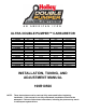
ULTRA DOUBLE PUMPER™ CARBURETOR P/N 0-76650RD 0-76650BL 0-76650BK 0-76650HB 0-76750RD 0-76750BL 0-76750BK 0-76750HB 0-76651RD 0-76651BL 0-76651BK 0-76651HB 0-76751RD 0-76751BL 0-76751BK 0-76751HB CFM 650 650 650 650 750 750 750 750 650 650 650 650 750 750 750 750 FINISH SHINY SHINY SHINY HARDCORE GRAY™ SHINY SHINY SHINY HARDCORE GRAY™ SHINY SHINY SHINY HARDCORE GRAY™ SHINY SHINY SHINY HARDCORE GRAY™ COLOR RED BLUE BLACK BLACK RED BLUE BLACK BLACK RED BLUE BLACK BLACK RED BLUE BLACK BLACK CHOKE ELECTRIC
TABLE OF CONTENTS: INTRODUCTION: .........................................................................................................................2 REMOVAL: ..................................................................................................................................2 INSTALLATION NOTES: .............................................................................................................3 CHRYSLER APPLICATIONS: .............................................................
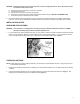
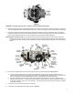
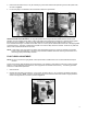
WARNING: Carefully protect the open end of the fuel lines, so that no foreign particles can enter. Wrap the end of the fuel line with a clean lint-free cloth. B. C. D. E. F. 3. Disconnect and mark all the vacuum lines to the carburetor. Disconnect the PCV hose. Disconnect the choke rod or heat tubes (if equipped). Disconnect and remove the throttle linkage and automatic kickdown linkage. SAVE ALL RETAINING CLIPS. Unbolt and remove the carburetor from the manifold.
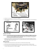
Figure 2—Ford applications 3. Remove the lock out screw from the kickdown lever (Figure 4). 4. Install the transmission kickdown spring between the transmission kickdown lever and spring perch on the solenoid/dashpot bracket (Figure 2).
Figure 5 WARNING: Overtightening may result in warped or cracked carburetor throttle body. 4. Before connecting the linkage, operate the throttle lever to ensure the correct travel (no sticking or binding), by opening to wide-open throttle and back to closed throttle several times. Correct any sticking or binding conditions before proceeding. 5. Reconnect the throttle and transmission kickdown linkage and throttle return spring (Holley® P/N 20-89).
9. Connect the fuel line. (Holley® 34-150 or equivalent) 10. In some cases, the existing fuel line will have to be cut and connected to the fuel line assembly from step 9 with a length of rubber fuel hose and clamp. WARNING: During the fuel line installation, DO NOT allow any foreign particles to enter the fuel lines, which could then cause flooding and may result in a fire. WARNING: Keep the fuel line away from the EGR valve (if equipped) on the intake manifold.
17. Shut off the engine and readjust the throttle operated transmission linkage, if necessary. On installations that have a kickdown-actuating switch on the passenger’s side of the firewall, it might be necessary to readjust it according to the manufacturer’s service manual. FORD APPLICATIONS WITH AUTOMATIC TRANSMISSIONS: With the engine off, push the transmission kickdown rod rearward until it stops and hold it in position.
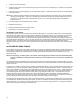
MANUAL CHOKE: 1. Connect the choke control cable (Holley® P/N 45-228) to the choke actuation lever, and lock in place with the choke cable lock screw (Figure 8). 2. Mount the outer sleeve to the cable clamp. 3. Actuate the choke cable through its full range of motion to ensure full choke operation. Adjust, as necessary Figure 8 IDLE MIXTURE NEEDLES: Idle mixture needles control the air/fuel mixture at idle. These have been preset at the factory and SHOULD NOT need any adjustments.
3. Now that the idle mixture is set, it may be necessary to go back and reset the idle speed using the curb idle speed screw, as shown in Figure 9. 4. If a vacuum gauge is not available, use a tachometer to obtain the highest RPM. Figure 10 Figure 11 ROUGH IDLE AND VACUUM LEAKS: If a rough idle persists after the engine has been started and the mixture screws adjusted, check for manifold vacuum leaks.
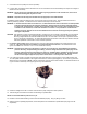
3. To adjust, shut down the engine. 4. Loosen the lock screw on top of the fuel bowl just enough to allow you to turn the adjusting nut. Hold the screw in position with the screwdriver. 5. Using a 5/8” wrench, turn the adjusting nut in the appropriate direction: Clockwise to lower fuel level and counterclockwise to raise the fuel level. NOTE: Many customers attempt to adjust the float level down by turning the adjusting nut clockwise, only to see the fuel level rise through the sight glass.
Figure 13 1. Figure 14 Change pump shooters until the smallest diameter nozzle that provides the crispest response is found. Figure 15 2. 3. Then change the pump cams and locations until the right cam is found that provides even more response. (Holley® offers a pump cam tuning kit part P/N 20-12) Finally, change the pump shooter once again, until the crisp response is maximized.
HOLLEY® PERFORMANCE PRODUCTS LIMITED WARRANTY NO OTHER WARRANTIES APPLY Holley® Performance Products warrants its new performance products to be free from defects in material and workmanship for a period of 90 days from date of purchase.