
Owners manual

6
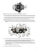
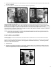
9. Connect the fuel line. (Holley® 34-150 or equivalent)
10. In some cases, the existing fuel line will have to be cut and connected to the fuel line assembly from step 9 with a length of
rubber fuel hose and clamp.
WARNING: During the fuel line installation, DO NOT allow any foreign particles to enter the fuel lines, which could
then cause flooding and may result in a fire.
WARNING: Keep the fuel line away from the EGR valve (if equipped) on the intake manifold.
If installation requires cutting the metal fuel line, cut the fuel line with a good tube cutter. This will minimize the chance of
producing metal chip particles. If a hacksaw must be used then metal chips must be removed.
WARNING: In all cases where the fuel line has been cut, it is essential that it be clean to ensure that no metal particles
enter the fuel bowl after the new carburetor installation. Remove the fuel line at the pump and blow the
line clean with compressed air. DO NOT use the procedure where the coil wire is disconnected, the engine
cranked for a few revolutions, and the fuel collected in a container. This procedure is unsafe because
sparking can occur either at the coil or at the distributor end of the coil wire and ignite any fuel spilled in
the engine compartment.
CAUTION: This carburetor contains in line Morain fuel filters. However, the use of a quality in line fuel filter, such as Holley®
P/N 162-523 is mandatory as a safeguard against possible flooding, which could result from unfiltered particles
becoming lodged between the fuel inlet needle and its seat. This can result in fire if a spark is present or backfire
occurs in the engine compartment. Air cleaner filter elements should be blown clean with compressed air at 6,000
miles and replaced at 12,000 miles to ensure maximum protection.
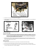
11. For electric choke hookup, attach the bayonet end of the long electrical lead supplied to the positive terminal on the
choke cap. The other end must be connected to an ignition activated 12-volt source. The distributor side of the
ignition coil is NOT a 12-volt source. It is a 7-9-volt source after cranking.
WARNING: Connecting the choke cap to the ignition or ignition coil could result in unacceptable choke operation,
poor fuel economy, and possible engine misfiring, since the voltage delivered to the spark plugs will be
severely reduced by the drain imposed by the choke cap. Suitable ignition activated 12-volt sources are
most electrical relays, as well as the leads to accessories, such as windshield wipers. DO NOT connect
this wire to the original equipment (O.E.) electric choke source. This may not be a 12V source.
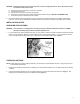
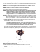
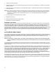
12. A 12”choke ground wire is provided (in the kit) and needs to be attached to a ground source on the intake manifold. The
.25” male spade terminal will attach to the negative terminal of the choke cap (see Figure 7). Use the 3/8” ring terminal to
attach the wire to the manifold. NOTE: Holley® recommends grounding to the intake manifold. An anodized surface is not
a good conductor of electricity and a proper ground may not be achieved.
Figure 7
13. Check the voltage source with a volt-ohm meter to ensure proper voltage and choke operation.
14. Start the engine and check the fuel lines and inlet fitting for possible leaks.
NOTE: The recommended fuel pressure is 5-7 psi.
15. Recheck to ensure that all existing vacuum hoses are attached properly. Plug any fittings not used.
16. With the engine at operating temperature, set the idle speed to the manufacturer’s specifications (see page 9 for idle
adjustment).