P/N 199R10382 2005 Mustang Wet Single Fogger Kit Kit Number 02121NOS OWNER’S MANUAL CONGRATULATIONS on purchasing your NOS Nitrous Oxide Injection System! Your system is composed of the highest quality components available. It should provide many miles of trouble-free performance when used correctly. If you have any questions regarding the performance of your system, call NOS Technical Service at 1-866-GOHOLLEY. NOTICE: Installation of Nitrous Oxide Systems Inc.
NOS nitrous oxide is legal for use in most states when used in accordance with state and local traffic laws. NOS does not recommend or condone the use of its products in illegal racing activities. NOS has not pursued California Air Research Board (CARB) exemptions for these kits, hence, they are not legal for use on pollution-controlled vehicles in California. A correctly installed NOS nitrous system should not alter the emission control performance of your vehicle under standard EPA test cycle conditions.
TABLE OF CONTENTS WHAT IS NITROUS OXIDE? .......................................................................................................4 Do’s and Don’ts of Nitrous Oxide..............................................................................................4 Chapter 1 Introduction to your NOS Nitrous Oxide Kit ..........................................................4 1.1 General Information .....................................................................................................
WHAT IS NITROUS OXIDE? NITROUS OXIDE… …Is a cryogenic gas composed of nitrogen and oxygen molecules …Is 36% oxygen by weight …Is non-flammable by itself …Is stored as a compressed liquid …Exists in two grades—U.S.P. and Nitrous Plus: U.S.P. is medical grade nitrous oxide; its common use is dental and veterinary anesthesia. It is also commonly used as a propellant in canned whipped cream. U.S.P. is not available to the public. Nitrous Plus differs from U.S.P.
These kits have been designed for safety and smoothness of operation. Nitrous oxide is injected into the engine only when the following conditions are met: Bottle valve is opened. System is armed. Engine is at wide-open throttle. RPM conditions are met. Horsepower and torque increases due to these kits will vary with engine displacement and modifications. Approximate power increase estimates can be made based upon the massflow of nitrous oxide into the engine.
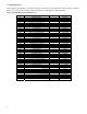
1.3 Kit Components Before beginning the installation of your NOS kit, compare the components in your kit with those shown in Figure 1 and listed in Table 2. If any components are missing, please contact NOS Technical Support at 1-866-GOHOLLEY.
Figure 1 Kit #02121NOS Wet Kit Components Chapter 2 Kit Installation 2.1 Bottle Mounting Instructions NOTE: Disconnect the battery ground before beginning installation. 2.1.1 Street Vehicles Accurate calibration of your NOS nitrous system depends on the bottle remaining at a stable temperature. Mount the bottle away from heat sources, such as the engine compartment or exhaust system, and away from windows, where the bottle is exposed to direct sunlight. 2.1.
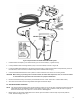
Figure 2 Nitrous Bottle Siphon Tube Orientation Figure 3 Nitrous Bottle Mounting Orientations 2.2 Bottle Orientation Bottle placement is critical to the performance of your NOS nitrous system. It is important to understand how the bottle valve and siphon tube are assembled to properly orient the bottle in your vehicle and ensure that it picks up liquid nitrous while undergoing acceleration.
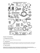
Figure 4 Exploded View of Kit #02121NOS Wet NOS System 1. Install the bottle nut adapter (1) and Teflon washer (2) on the nitrous bottle (3). Tighten securely. 2. Loosely install the bottle mounting brackets (4 & 5) on the nitrous bottle, as shown in Figure 3E. 3. Locate the bottle/bracket assembly in the desired mounting location, ensuring that the location will provide easy access to the bottle valve, hose connection, and bracket clamp bolts to facilitate bottle changing. 4.
2. Install the Soft Plume Nozzle (22), taking into account the length of the nitrous and fuel supply hoses and the intended location of the solenoids. Take into account that the nozzle mounting bung (21) needs to be restrained during final installation, and accessibility of a tool is important. Make sure the nozzle and feed lines will not interfere with engine components or accessories and will not interfere with the hood when closed.
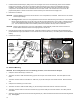
Figure 6 8. Mount the solenoid assembly to the driver’s side foremost valve cover bolt. See Figure 6. Ensure that the assembly and lines do not interfere with engine accessories or body parts, and that hoses reach the Soft Plume nozzle inlet ports without being stretched or kinked. 9. Securely mount the solenoid assembly. 2.6 Solenoid / Soft Plume Nozzle Hose Connection 1. Select the proper nitrous and fuel jets (13-16).
2. Install the 4AN fitting (12) into the injector block with Teflon paste, while secured in a soft jaw vise. Tighten securely. See Figure 9. WARNING! Do not tighten fittings while installed on the fuel rail. Install these while secured in a soft jaw vise. 3. Thread the 90° end of the 6” 4AN hose into the fitting in the injector block (hand tighten and add a 1/2 turn). See Figure 10. 4. Insert the “injector block” with O-ring pressed into the rail. Lube the o-ring with o-ring lube or Vaseline.
Figure 12 Electric Wiring Schematic 2.9 Electrical System Installation (WOT/Window Switch) Refer to Figure 12 and the procedures in this section for electrical system installation. WARNING! Death or injury may occur from working on a charged electrical system. 1. Disconnect the car battery at the ground cable (if not already done). 2. Install the WOT/Window Switch (27) as follows: 3. A. Find a suitable mounting location away from heat and vibration (ex. firewall). B.
Components Figure 13 Snap in rocker switches & use backing plate with purge switch. Figure 14 Installed Figure 15 Hand tighten the purge switch. Installation complete Figure 16 Figure 17 4. Install the wiring relay and relay harness in the engine compartment near the battery. The relay’s orange wire should reach the battery (+) terminal. 5. Connect the orange relay wire to the battery (+) terminal. Install a 15 AMP fuse into the fuse socket. 6. Connect one wire from each solenoid together.
Coil #3 is closest to the firewall. Coil #1 is closest to the radiator. Figure 18 Figure 19 11. Connect the brown / yellow striped wire on the WOT/Window Switch to the green / white striped wire of coil #3 (cylinder 3) on the car. See Figure 19. 12. Connect the black wire of the WOT/Window Switch to a ground. 13. Connect the yellow / white striped wire on the WOT/Window Switch to the yellow / white striped on the car TPS sensor. See Figure 20. Figure 20 14.
2.10 WOT/Window Switch Troubleshooting- Verifying the operation of the NOS WOT/Window Switch NOTE: NOS highly recommends that the user NOT change the factory WOT/Window Switch settings. The WOT/Window Switch should be set at the - 3000 rpm (low) and 6000 rpm (high) - default settings. With the NOS WOT/Window Switch, these values are adjustable, but altering them is not recommended. The NOS WOT/Window Switch also has a TPS/Microswitch built into the unit. The default and recommended setting is 4.3 volts.
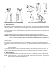
Chapter 3 Routine Maintenance 3.1 Nitrous Solenoid Filter When nitrous bottles are refilled they can become contaminated with debris, if the refiller does not have an adequate filter in their transfer pump mechanism. Contaminants in the bottle will eventually become lodged in the nitrous solenoid filter fitting. You should periodically (after every 20-30 pounds of nitrous usage) examine the mesh in the nitrous filter for debris. To clean the filter, follow the following steps: 1.
Figure 23 Exploded View of a Typical Solenoid Appendix A Troubleshooting Guide The troubleshooting chart on the following pages should help determine and rectify most problems with your installed NOS system. If you still need assistance determining or fixing problems, call the NOS Technical Support at 1-866-GOHOLLEY. PROBLEM No change in engine speed when the fuel solenoid is activated (Preparing for Operation— Chapter 4). POSSIBLE CAUSES System wired incorrectly. Restricted fuel line.
Mismatched N2O/fuel jetting. Excessive fuel pressure. Loose nitrous solenoid wiring. Malfunctioning nitrous solenoid. No change in performance when system is activated. System wired incorrectly. Loose ground wire(s). Malfunctioning arming switch. No power to arming switch. Malfunctioning throttle microswitch. Engine detonates mildly when system is activated. Engine detonates heavily when system is activated. High-rpm misfire when system is activated. Surges under acceleration when system is activated.
Nitrous Oxide Accessories NOS systems are calibrated for optimum performance with a bottle pressure of 900-950 psi. The pressure will change with temperature. Heater kits are thermostatically controlled to keep the bottle near 85° F to provide correct pressure. Bottle Heater (P/N 14164NOS) is available for 10 & 15 lb. bottles. Insulating the bottle helps maintain pressure by keeping heat in the bottle when it’s cold, or heat out when it’s hot outside.