COMMANDER 950 TOTAL ENGINE MANAGEMENT SYSTEM ELECTRONICS AND FUEL INJECTION MANUAL 199R-10149-5 NOTE: These instructions must be read and fully understood before beginning installation. If this manual is not fully understood, installation should not be attempted. Failure to follow these instructions may result in subsequent system failure. Copyright © 2001 by Holley Performance Products, Inc.
INTRODUCTION ................................................................................................................................................... 4 1.0 TERMS & DEFINITIONS OF FUEL INJECTION MANAGEMENT SYSTEMS.............................................. 5 1.1 FUEL MANAGEMENT SYSTEM ........................................................................................................................... 5 1.2 THROTTLE BODY INJECTION (TBI)....................................................
9.0 REQUIRED ADDITIONAL EFI TUNING......................................................................................................... 36 10.0 ALPHA-N TUNING....................................................................................................................................... 50 11.0 DATA LOGGER........................................................................................................................................... 53 APPENDIX 1 COMPLETE SOFTWARE OVERVIEW ..............
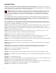
INTRODUCTION Thank you for your purchase of the Holley Commander 950 Fuel Injection System. This tuning manual is designed to take all of the guesswork out of tuning your Commander 950. Holley is dedicated to providing products for our customers that not only outperform your expectations, but also are easy to install and tune. NOTE: We highly recommend that you carefully read through all the manuals included with your system before installing and tuning your Commander 950 Fuel Injection System.
Appendix 7 covers the description of fuel injection systems, including: combustion principles and air/fuel ratios, emissions and performance, and engine management systems. These engine management systems consist of: air management, fuel management, and ignition timing management. Appendix 8 covers the engine application and the selection of your fuel management system components, including: injector fuel flow and fuel pressure. Appendix 9 covers the two kinds of fuel pumps and their flow characteristics.
1.3 Multi-Point Fuel Injection (MPFI) A multi point fuel injection systems meters the fuel to each cylinder individually via the fuel injector located just upstream of the intake valve. The fuel is supplied to the injectors via a fuel pump. The MPFI is superior to the TBI systems because it will generate better fuel economy, higher power output and improved throttle response. These advantages are mainly due to the proximity of the injector to the intake valve and better fuel atomization.
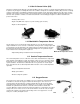
1.6 Fuel Injectors There are basically two approaches in delivering the fuel to the engine: • Above the throttle plate as in throttle body injection • In the intake port toward the intake valves as in multi-point injection The fuel injector is continuously supplied with pressurized fuel from the electric fuel pump. The pressure to the injector is maintained constant by the fuel pressure regulator.
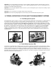
§ 3 Ball-on-a-stick injector. This metering design is mostly used in the director plate application. The seal is achieved between a conical seat and a spherical plunger. The director plate has the function of metering the fuel and generating the required spray geometry. Fuel flow is adjusted by the size of the hole machined into the director plate and the spray geometry is adjusted by the orientation of the holes in the director plate.
1.9 Idle Air Control Valve (IAC) The IAC is located in the throttle body of the TBI and MPFI. The valve consists of a stepper motor that adjusts the position of its pintle to vary the bypass air during idle and of idle conditions. During the closed throttle condition (idle), the ECU constantly compares actual engine speed with the programmed desired engine speeds.
1.13 Electric In-line Fuel Pump The function of the electric fuel pump is to deliver pressurized fuel to the fuel injection system. The ECU activates the fuel pump relay to operate the fuel pump when the ignition switch is in the On or start position. The pumps are designed to match certain flow and pressure specification for the engine application. In TBI applications, the fuel pump must supply enough fuel flow for the engine Wide-Open Throttle (WOT) output at 15 to 20 psi.
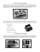
1.16 Main Fuel Filter The function of this filter is to eliminate any contaminants after the fuel pump. These are either small enough to pass through the fuel filter of the pump inlet or are generated by the fuel pump. This fuel filter is also of the cartridge type, but is designed to sustain much higher fuel pressures than the fuel pump inlet filter. These filters have a rating of 10 microns. NOTE: This fuel filter is required to avoid fuel injector damage. Main Fuel Filter 1.
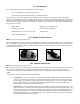
O2 Sensor Voltage 1.21 Open Loop Open loop defines the engine operation where the fueling level is calculated by the ECU with only the input signals from the throttle position sensor (TPS), from the coolant and/or air charge temperature, and from the manifold absolute pressure (MAP). For additional information, see Appendix 7 (Description of Fuel Injection Systems) 2.
The Air Temperature Sensor monitors the temperature of the incoming air. This tells the ECU what the outside temperature is and allows the ECU to adjust the fuel for this. The Coolant Temperature Sensor tells the ECU the temperature of the engine and will add extra fuel when the engine is colder, just like the choke on a carburetor. Using these inputs, the ECU can then calculate how much fuel to inject. The fuel system is made up of several basic components.
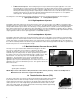
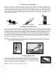
2.1 Speed Density 1. 2. 3. 4. 5. Engine speed (1000 RPM) and manifold pressure from the MAP sensor (38 kPa) are read by the ECU. From these values, it obtains a number from the base fuel map (32). The ECU then looks at the reading from the Air Temperature Sensor and may modify the fuel value. In this case it adds .8% more fuel. The ECU looks at the reading from the Engine Coolant Temperature Sensor and may further modify the value.
2.2 Alpha-N An Alpha-N system is similar to a speed density EFI system, except that for step 1, the ECU will look at engine speed and the position of the Throttle Position Sensor, instead of the MAP Sensor, to determine the value from the base fuel map. The following flowchart (Figure 2) illustrates this example. 40 1000 RPM ENGINE SPEED Key: THROTTLE POSITION (TPS) Sensor Data Input 32 BASE FUEL MAP VALUE ECU Calculations and Adjustments 47°F 100.
3.0 SKILL LEVEL REQUIRED Installation of the COMMANDER 950 intake system and the ECU requires approximately the same level of skill and experience to replace or service an induction system consisting of a carburetor and conventional intake manifold (as well as basic wiring skills for the installations of the ECU). Tuning of the system requires basic computer skills and a basic knowledge of engine and fuel injection principles. The information needed to tune this system is included in this manual.
5.1 Step-by-Step Wiring Harness Installation NOTE: It is advised to leave the battery completely disconnected until the installation of the entire system is completed. 1. ECU MOUNTING – The ECU should be mounted as far away from the ignition box as is feasible (minimum 6”). The ECU must be installed in the vehicle in a location free from moisture and dirt. The glove box area is usually a good location in most vehicles. There are sheet metal screws included for this purpose. The ECU must be grounded.
1. BLACK WIRE - Connect the black wire to a solid chassis ground with the ring terminal provided. The best place to connect is the negative side of the battery. 2. RED WIRE - Connect the red wire directly to the positive side of the battery with a ring terminal provided. 3. RED/WHITE WIRE - Connect the red wire with the white stripe to a 12 volt source which only has power when the ignition switch is on. Make sure it has power when the key is in the “start” position also. 4.
Crank Trigger CD Ignition Systems – The Commander 950 can control the timing on any engine that uses a crank trigger (magnetic or Hall effect) and capacitive discharge ignition box. Non-Computer Controlled Inductive Ignition Systems – Any inductive (non-CD) ignition system (most stock ignition systems are inductive) can be used to provide an RPM signal to the Commander 950. These systems will not allow the Commander 950 to control ignition timing.
6.3 Software Operation and Navigation The Commander 950 is a Windows-based software. It functions the same as all other windows software. Pull-down menus are selected with the mouse. These are then opened to view the various tables. Software Data Capture – When a window is opened, the software checks for the ECU. If it is present (powered up and connected to the serial cable), the computer will get the latest data from the ECU.
Mouse Free Navigating – Often it is easier to not use the mouse when operating a laptop. The C950 software can be operated without the use of a mouse. From the main window, press “Alt” and then the underlined letter of the window or menu you want to open (i.e. press “Alt” and then “F” to open the “file menu”). Different locations can be navigated by pressing the “Tab” key.
NOTE: There is a vacuum line going to the fuel pressure regulator. This is needed to compensate for vacuum present in the intake manifold. Make sure you always use this vacuum line. When the engine is running and the vacuum line is hooked to the regulator, the pressure seen on the fuel pressure gauge will be lower depending on how much vacuum is present. 2 inches (Hg) of engine vacuum will lower the fuel pressure 1 psi. For example, 15 inches (Hg) of engine vacuum will lower the fuel pressure about 7 psi.
Figure 5 Engine Parameters Screen Record your selection in the spaces provided. __________Cylinders – Pick 4, 6, or 8 __________Port Fuel Injection or Throttle Body Injection – Select Multi-Port or Throttle Body fuel injection __________Ignition Type – See page 63-64 (Appendix 1—Hardware Settings) FOR DETAILED INFORMATION if you are not absolutely sure what type of ignition you have. If you have a computer-controlled (has NO mechanical or vacuum advance) GM HEI (1981 and up), select “GM HEI”.
9. ¨ SAVE PARAMETERS It is recommended that you save your map to the computer hard drive anytime you make changes, that way you can always go back to a previous version. At this time you should save that map that has the correct engine parameters. To save the map perform the following: A. Turn the ignition on. B. Go to “File” and “Retrieve ECU Data” C. Go to “File” and “Save Data to Disk” D. Select the directory that you want to save it to E. Type in a name for the map F.
Check the following sensor outputs. After each, record the value in the space provided. ¨ __________MAP (Manifold Air Pressure) – The manifold air pressure when the engine is not running should be between about 88 and 94 with the engine not running. In higher elevations it will be lower. Possibly as low as 75-80. ¨ __________TPS (Throttle Position Sensor) – The position of the TPS needs to be greater than 5 with the throttle closed and when the throttle is fully opened, it must be less than 255.
8.0 STEP-BY-STEP BASIC TUNING The following is a step-by-step guide to perform basic tuning that will be required with all applications. TIPS: Tune one parameter at a time. Don’t change things unless you know what they do. Follow the instructions. They provide a methodical tuning plan. This section is designed to help you with 75% of the tuning you need to perform. Fine tuning information is covered in Section 9.0. Fine tuning is required to realize the performance that EFI will deliver.
2. CHECK TIMING If the ECU is getting an RPM signal, the next best thing is to make sure that the ignition is firing. To check this, connect a timing light to spark plug #1, and make sure that it is firing while it is cranking. If it is, try to see approximately what the timing is on the harmonic balancer. If it is not between approximately 0 and 40° BTDC, then that may be why it will not start. Adjust the distributor until the timing is about 10° BTDC.
Figure 9 Startup Enrichment Table 4. STARTUP / STARTS AND STALLS If the engine starts and then stalls, it most likely needs more air and/or fuel. There are several areas that may need tuning that relate to fuel. For simplicity’s sake, at this time, we are going to stay in one area, the main fuel map. The other areas that will likely need to be changed are the coolant temperature modifiers and the afterstart enrichment. If these areas are not ideal, we will just tune the fuel map now to compensate.
Figure 11 Example of Fuel Map with Graphical Representation TIP: This red box will move around. Notice where the red box is when the engine starts. If the engine stalls, leave the key on and increase the values in the area where the engine was trying to idle. Raise this area in increments of 5 units at a time. A typical small block or big block with 24-36 lb./hr. injectors should usually only need a number between 22 and 40 in the fuel map depending on many variables.
Figure 12 Spark Map with Engine Idling When the engine is running, the area that it is getting its timing advance from will be highlighted in red. The advance is also shown in the data monitor (spk adv). With a timing light, check the advance at the crankshaft. The value at the crankshaft needs to be the same as the value on the data monitor.
Figure 13 Fuel Map Showing Proper IAC Position For more information on how an IAC works, see Appendix 1—Idle Air Control. 7. FUEL MAP TUNING (LOW SPEED) The next step is to adjust the base fuel map. The method used requires that an oxygen sensor is installed and operating properly. See Appendix 1—O2 for VERY important information about oxygen sensor operation and installation. Most of the base maps should be set so that the engine will go closed loop at idle with engine temperatures above 130° F.
Figure 14 Engine Idling with Proper O2 Mod The number should be about 85 -100 when tuned properly. This means the base map is slightly richer than 14.7:1, which will promote good driveability. If it is over 100 it is lean and if it is less than about 85-90 it is too rich. The software limits the amount of compensation possible, although this value is programmable. The base maps have the limit set to +/-19%.
Figure 15 Example of Smooth Fuel Graph To modify the graph, move the pointer by using the arrow keys. When you want to raise or lower a point, hold the shift key down and use the arrow keys to raise or lower a point one value at a time. Holding the Control (Ctrl) key and using the arrow keys changes the value by 5. The graph can be rotated by using the arrows below and to the right of the graph.
LESS THAN 85 SUBTRACT FUEL PULSE WIDTH* AND SMOOTH SURROUNDING CELLS** “O2 Mod” ON THE FUEL MAP IS… ** Always listen for pinging (preignition). Stop driving immediately, bring up the spark map, and subtract ignition advance in the area pinging is encountered. ADD FUEL PULSE WIDTH* AND SMOOTH SURROUNDING CELLS BETWEEN 85 AND 105 DOES THE ENGINE RUN WELL? * The actual amount of fuel or timing advance that needs to be added or subtracted depends upon how far the map is off.
To tune WOT, find a safe place where the vehicle can be accelerated to legal speeds. Again, you need one person driving and one person tuning and monitoring. Open the main fuel map. The sensor that needs to be monitored carefully is the oxygen sensor voltage output. This is found on the data monitor (O2 V). This voltage is also shown in large numbers on the Rich/Lean indicator. When this voltage is below .45 volts, the color will be red. When this voltage is between .45 and .75 volts, it will be yellow.
(RED OR YELLOW) LESS THAN 0.75 STOP IMMEDIATELY! ADD FUEL PULSE WIDTH IN LEAN AREAS* AND SMOOTH SURROUNDING CELLS WATCH THE “O2 (V)” VALUE ON FUEL MAP ** Always listen for pinging (preignition). Stop driving immediately, bring up the spark map, and subtract ignition advance in the area pinging is encountered. SUBTRACT FUEL PULSE WIDTH* IN RICH AREAS AND SMOOTH SURROUNDING CELLS** (GREEN) BETWEEN 0.75 AND 0.
NOTE: In the idle air control motor, there is simply a valve that lets extra air into an engine. It is used to raise the idle when an engine is cold and to maintain a desired rpm when a vehicle with an automatic transmission is placed in gear. You must set the throttle plates to provide the majority of the airflow at idle to an engine. The IAC just supplements this. If your idle is higher than you program it to be, you have to close the throttle plates.
B. AE Correction vs. Coolant Temperature – The second line down says “AE correction vs. Coolant temperature”. These numbers are to modify the TPS based acceleration enrichment when the engine is colder. Just like the coolant temperature modifiers, a number 110 for example adds 10% more acceleration enrichment fuel. When the engine temperature gets up to operating level, the numbers should read 100. Usually you don’t need to make the numbers much more than 110 when it is cold.
REV ENGINE SLOWLY IN NEUTRAL RAISE LEFT 6 BOXES OF THE “Pulse Width – Rate of Change of TPS” TABLE 0.3 mSec* NO DOES THE ENGINE REV SMOOTHLY? YES * Most of the time, fuel pulse width needs to be added to these tables if the engine doesn’t rev smoothly. A lot of fuel needs to be added before the engine stumbles due to too much fuel. As always, if the symptom gets worse, try taking fuel out. Spark advance can also have an effect.
* Most of the time, fuel pulse width needs to be added to these tables if the engine doesn’t rev smoothly. A lot of fuel needs to be added before the engine stumbles due to too much fuel. As always, if the symptom gets worse, try taking fuel out. Spark advance can also have an effect.
3. Spark Advance - The next area that can be reviewed is the spark advance map. The base spark maps provided should provide a good performing baseline but are conservatively low for some applications and may need less for others. Optimizing timing is very important for best idle, peak safe power, and best driveability. Most people do not understand the benefits of having computer-controlled timing. With mechanical advance you are limited to the advance curve of the distributor.
Also make sure you listen for engine knock, especially in the peak torque area when you are changing timing. If you drag race, sometimes putting in more timing in the map area where you stage and launch will help 60 foot times. Usually, there is little to be gained with a few extra degrees of timing at WOT, so be somewhat conservative or you may damage your engine. A knock sensor is not designed so that you can run a lot of timing and let the knock sensor “pull it back to the best timing”.
Figure 24 Poor Spark Map at Idle Figure 25 Poor Fuel Map at Idle and Cruise 43
C. As was mentioned before, another key for best idle is to adjust the throttle plates so the idle air control motor is not open much or at all when the engine is hot and in neutral. To do this, look at the data monitor and the IAC Position. It should read 10-15 with the engine at the programmed desired idle. If the IAC is too far open, the desired cold idle speed will not be maintained. If the idle speed is greater than desired, close the throttle plates. D.
Desired Idle – The engine idle speed will be controlled by the ECU and can be changed at different temperatures. If the engine is cold, the idle speed will need to be higher than if the engine is warm for best idle stability. These values are very specific to each application. Stock engines can idle as low as 600 RPM and some race engines need to idle over 1300 RPM. Normally, the cold idle should be about 200-300 rpm higher than the hot idle for most engines.
TIP: As a guideline a TPS position that is between 2/3 and 3/4 throttle usually works fine for naturally aspirated engines. This is an important value, but does not need to be exact down to 5 or 10 numbers. A supercharged or turbocharged engine will have this value set much lower. Normally, this value should be 17-25% of WOT. O2 Compensation Step Size – This table specifies how much fuel the ECU will take out or add to the current volume on each step in an attempt to bring the air/fuel ratio to ideal.
Figure 30 Air and Coolant Temperature Modifier Table Figure 30 shows an example of the coolant temperature enrichment table. With the Commander 950, you enter a number that multiplies whatever fuel value you are using from the base fuel map (based on the RPM and load of the engine). This number needs to be larger, the colder the engine is. It is very simple how it works so don’t try to overcomplicate it. If you enter a number such as 120, then the base fuel map will be increased by 20%.
Figure 31 Fuel Map Showing Coolant Mod and Afterstart Mod After Engine Start To tune the Coolant Temperature Enrichment, make sure the vehicle sits overnight to completely cool down. Start the vehicle. If it stalls, start it again. Try to keep it running for a few seconds with the gas pedal. If you can’t at all, go to the Coolant temperature enrichment. With the key on and the engine not running, see what cell is highlighted in the coolant temperature enrichment table.
START THE ENGINE INCREASE AFTERSTART ENRICHMENT 5% AT THAT ENGINE TEMP* * The actual amount of fuel that needs to be added depends upon how far the settings are off. YES DOES THE ENGINE STALL IN THE FIRST 2 SECONDS? NO ** The settings may need fine tuning as varying cold start conditions change (summer to winter, etc.
Afterstart enrichment is found in “Fuel” and then “Startup Enrichment”. There are three parts of this area that deal specifically with afterstart enrichment. They are: Ø Afterstart Enrichment – Works the same way as the coolant temperature enrichment. If the number is 140, then 40% more fuel is added from the base fuel map when the vehicle starts.
a large increase in fuel. This makes the fuel map very uneven. This causes poor driveability that is hard or impossible to resolve with mapping. If this same engine were mapped using speed density operation, this large change in airflow would create a large change in the position of the fuel map. This would allow for the map to be smooth creating a much better driveability. It is always best to run a throttle body design that has the most linear increase in airflow possible.
Figure 34 Typical Alpha-N Fuel Map Mapping is the same as speed density from the aspect that the area on the base fuel map that you are obtaining fuel map values from will be highlighted in red. Drive the vehicle at different throttle positions and engine speeds to modify the fuel map as needed. Closed loop feedback and oxygen sensor voltage can both be used for feedback just like speed density.
11.0 DATA LOGGER Figure 35 Main Datalogger Screen The Commander 950 includes a data logger that serves many useful purposes. It can be used for logging runs at the dragstrip or used to analyze data when tuning a vehicle. To start the data logger, first select “File”, and “Log Data”, after the datalogger is opened. This will bring up the window below (Figure 36) asking you to specify a filename. Select the directory you want to save it under and enter a filename.
After you enter a filename hit “OK”. The “Trigger” screen below (Figure 37) will appear. Figure 37 The trigger screen (Figure 37) allows you to start the data logger immediately or wait for a trigger point. The trigger point is a selectable input such as RPM, TPS, and more. You can input a value for any of these. When the system reaches this value it will automatically start. The example above would wait for an engine rpm greater than 3000 to start taking data.
Figure 38 TIP: If more than 5,000 data points are taken, the software will automatically split them up into separate files. 5,000 data points amount to 5-8 minutes depending on the computer. TIP: For example, if you take 15 minutes of data and name the data file TEST, you will have 3 separate files automatically saved. When you go to load a file you will see three file names. They will be TEST, TEST01, and TEST02. The software automatically adds a 01, 02, etc. at the end of extra files.
APPENDIX 1 COMPLETE SOFTWARE OVERVIEW Appendix 1 provides a description of all the software functions. It is not intended to describe how to tune an engine, but rather to provide one section that details all the different screens that will be used. FUEL – These allow the user to alter the fuel specific parameters of the engine. Main – This is the primary table the engine uses when it is running. Each box or “cell” contains a number representing the injector pulse time.
DATA MONITOR – Used for monitoring real-time engine parameters Both the Main Fuel Map and Spark Map screens have a readout of real-time engine parameters above the graph. This is an essential tool when tuning an engine. The following is an explanation of each readout: 02 Mod – Indicates the percent modification to the base fuel injection pulse width only when the engine is operating closed loop. 100 would mean that no correction is occurring.
Fuel Graph – This is a graphical representation of the fuel cell values. When properly tuned, the fuel map should be smooth. The graph mode can be used to refine the fuel values into a smoother curve. You will want to view some of the supplied fuel maps to see what a fuel graph should look like once finished. Once you become familiar with engine tuning, you can often tune an engine very close by tuning 10 to 15 points and using the fuel graph feature to fill in the rest.
Afterstart Holdoff – These parameters control the number of revolutions the ECU waits before adding the afterstart fuel enrichment. Afterstart Decay Rate – Rather than deleting the afterstart enrichment after the afterstart holdoff period all at once, the ECU allows the user to program the speed of decay. The number in each cell corresponds to the number of revolutions to allow between 1% fueling changes. The greater the number, the slower the afterstart enrichment will decay.
AE of MAP vs. Coolant Temperature (%) – Colder engine temperatures may require different transitional fueling requirements. This table allows the user to tailor the synchronous fueling to the engine temperature. Numbers are percentage based with number below 100 subtracting a percentage from the base Delta MAP and numbers higher adding a percentage to the base Delta MAP. Modifiers – The following three tables adjust the base fuel delivery according to various external sensors.
Figure 44 Figure 45 61
Idle spark control – These parameters allow the ECU to adjust the idle spark timing to control the engine idle speed. This function can be turned on or off. The P term: adjusts the timing to assist in idle stabilization. The D term: compensates for overshoot. The Max TPS for idle: tells the ECU when to stop trying to adjust the engine timing to control engine speed. Figure 46 Knock Control – The ECU can optionally be equipped with a GM knock module and a corresponding knock sensor.
Hardware Settings (Hdwr Settings) Figure 48 Engine Parameters Engine Parameters – Base engine parameters that must be adjusted before the engine is started. Number of cylinders - Select from 4, 6, or 8 cylinders. Only even-fire engines can be used. Most engines are even fire except for some V6 engines. Open or Closed Loop operation. See the EFI fundamentals Section 1.20 & 1.21 for important information on open and closed loop.
Inductive Pickup – Use with a magnetic pickup crank trigger. See Appendix 10 for wiring specifics. Ford TFI – Use with Ford TFI electronic distributors. Allows for the Commander 950 to control ignition timing. Requires adapter cable PN 534-139, which is included in Ford 5.0L MPFI kits. GM HEI – If any of the following ignition systems are used, select GM HEI. 1981 and up GM small and large cap computer controlled HEI distributors. Allows for the Commander 950 to control timing.
Rev. limiter high RPM – At this rpm, the engine will stop injecting fuel to limit the speed of the engine in an attempt to protect the engine from self-destruction. Rev. limiter low RPM – Once the ECU has quit injecting fuel because the rev. limiter has been hit, this is the rpm the engine will have to drop below before the ECU starts injecting fuel again. This value is usually set 100 to 500 rpm lower than the rev. limiter high rpm depending on the desired effect.
Figure 51 Idle Air Control Desired Idle – The engine idle speed will be controlled by the ECU and can be changed at different temperatures. If the engine is cold, the idle speed will need to be higher than if the engine is warm. This is because the oil will be thick and the friction internal to the engine will be greater. IAC Parked position – After the ECU is told to shut off, it will command the IAC motor to this location.
Hot Start Delay – The amount of time the engine will wait before entering closed loop operation when the engine is restarted while still hot. This should be about 30 seconds. RPM to Enter Closed Loop – Any rpm above this point will activate closed loop. RPM to Return to Open Loop – If the rpm falls below this point, open loop operation will occur. This setting should be about 100 rpm below the rpm to enter closed loop. This is so that the ECU doesn’t not “hunt “ between open and closed loop operation.
Tuning a Race Engine: By far the best way to tune a high horsepower race engine is on the engine dyno. The dyno must provide certain feedback as to the brake specific fuel consumption (BSFC), and/or Air/Fuel Ratio to help initial tuning. Exhaust gas temperatures also provide helpful feedback. If the engine is already installed in the vehicle, a chassis dyno can be used for power measurement but is not near as useful as an engine dyno.
1. Fuel Injection Type - In the engine parameters screen, Throttle Body Inj. must be selected for the fuel injection type. 2. TBI Switch – If a TBI system with progressive throttle linkage is used, the following two parameters must be set correctly or significant problems will occur. They also need to be adjusted with a non-progressive TBI system. With a progressive linkage, the rear throttle plates do not open until the throttle is approximately 1/3 open.
Appendix 3 Tuning Troubleshooting Engine will not Start There are several different reasons why an engine will not start. - Make sure that the engine is receiving a RPM signal. To verify this, see if the “Fuel Pump On” which is located on the data monitor on the base fuel map screen, is highlighted in red (indicating the fuel pump is turned on). If it is not red, the ECU is not getting an RPM signal. There are several things to check, make sure everything is receiving power as it should.
Engine Hesitates When the Throttle is Applied The following tuning will help alleviate hesitation when the throttle is applied. The flowchart (Figure 21) shows a graphical representation. - Injection volume map not correct. When the throttle is applied to accelerate, the area on the injection volume map that the ECU reads from changes (rpm and load increases).
START THE ENGINE INCREASE AFTERSTART ENRICHMENT 5% AT THAT ENGINE TEMP* * The actual amount of fuel that needs to be added depends upon how far the settings are off. YES DOES THE ENGINE STALL IN THE FIRST 2 SECONDS? NO ** The settings may need fine tuning as varying cold start conditions change (summer to winter, etc.
Appendix 4 GENERAL TROUBLESHOOTING Double check ALL wiring connections and system voltages BEFORE replacing components. If you suspect an ECU or component failure, check all other possible problems before replacing a component. CONDITION 1. Fuel Pump fails to operate 2. No fuel from injectors 3.
Appendix 5 TESTING AND TROUBLESHOOTING ELECTRICAL COMPONENTS Testing Relays 1 - To test the relays, apply a 12 volt power source to terminal 85 and ground terminal 86. The relay should click. Using an ohm meter, check for low resistance across terminals 87 and 30. 2 - With the 12 volt power source removed from terminal 85, check for high resistance across terminals 87 and 30. 3 - If the relay does not perform as described above, the relay is defective and must be replaced.
3 - Check the voltage on the TPS with the throttle closed. It should be between approximately .3 and .8 volts. While watching the voltmeter, move the throttle lever from fully closed to fully open. The voltage should change smoothly from the idle voltage to 4.5-5.0 volts. If the reading fluctuates, the TPS is intermittent and should be replaced. If the voltage is range, turn the ignition key off, remove jumper wires and reconnect the TPS.
Appendix 6 OXYGEN SENSOR EFFECT ON PERFORMANCE The oxygen sensor monitors the exhaust gases and outputs a voltage that corresponds to the air/fuel mixture. The range of voltage output from the oxygen sensor is 0.0 to 1.0 volts. A lean fuel/air mixture gives a lower oxygen sensor output voltage while a rich fuel/air mixture gives a higher oxygen sensor output voltage. The stoichiometric or chemically perfect fuel/air mixture gives an oxygen sensor output of approximately 0.5 volts.
Figure 57 O2 Sensor Voltage Appendix 7 DESCRIPTION OF FUEL INJECTION SYSTEMS Combustion Principles and Air / Fuel Ratios During combustion of any substance a required surface to mass ratio and a correct amount of oxygen must be must be available. In internal combustion engines these requirements are controlled by the fuel management system. Optimum surface to mass ratio is achieved by finely atomizing the fuel, while the right air fuel ratio is achieved by metering fuel in proportion to the induced air.
92 FUEL 86 84 A/F=14.7:1 A/F=12.6:1 74% AIR 88 92.5% AIR 90 93.5% AIR Percent [%] 94 6% FUEL 96 7.5% FUEL 98 6.5% FUEL 100 AIR 82 80 A/F=15.4:1 Figure 58 Percent Air vs.
Emissions and Performance Internal combustion engines generate power by burning air and fuel mixtures. In gasoline fueled engines, the proportions of air and fuel (air/fuel ratio) are critical for optimum combustion. The quality of combustion is directly related to engine power output and its running characteristics. The goal of a fuel metering system is to generate a homogenous air/fuel mixture. A homogenous mixture of 14.
The volumetric efficiency is a ratio that describes how efficiently the engine acts as an air pump for its size. The volumetric efficiency is calculated by the following equation: Volumetric efficiency (VE) = Actual Volume of Air/Fuel induced into the Engine Engine Displacement In general, the volumetric efficiency of naturally aspirated engine configuration is as follows: Engine Configuration Stock Engine Modified Engine Highly Modified Engine Supercharged VE 0.85 0.93 0.98 1.
(lambda sensor) oscillates between rich and lean within a defined operating window. As the O2 sensor switches, the injector pulse width is adjusted by the ECU until the lambda sensor switches again to the opposite condition. This switching operation continuously supplies the ECU with the information needed to maintain a stoichiometrically correct combustion. Three wire O2 sensors are designed to indicate an air/fuel ratio of 14.7:1.
NOTE: If the application requires a static flow rate that falls in between two available injectors always use the next larger injector. For the example above if only 25 Ib./hr. and 30 Ib./hr. injectors are available, choose 30 lb./hr. injectors. Fuel pressure In certain occasions matching of the injectors' static fuel flow for a specific engine application cannot be done due to injector availability or the static fuel flow step between the available injectors is too large.
Appendix 9 FUEL PUMPS Fuel pumps produce volume. Fuel pressure regulators make fuel pressure. It is important to understand this principle. An adjustable fuel pressure regulator can be used to raise or lower fuel pressure, if necessary. When doing this, one must ensure that the fuel pump can maintain the needed volume at higher pressures. Systems come with one of two kinds of fuel pumps. Systems with 30 lb./hr. injectors and smaller come with the “black” Holley pump (sales PN 512-105).
Appendix 10 WIRING DIAGRAMS Figure 61: Figure 62: Figure 63: Figure 64: Figure 65: Figure 66: Figure 67: Figure 68: Figure 69: Figure 70: Figure 71: Figure 72: Figure 73: Figure 74: Figure 75: Commander 950 to Ford TFI Ignition Using Ford Computer Controlled Distributor, TFI Module. Commander 950 to Aftermarket Ignition Using Ford Computer Controlled Distributor, TFI Module. Commander 950 to GM HEI Using Mechanical and Vacuum Advance 4-Pin Module Distributor.
COMMANDER 950 TO AFTERMARKET IGNITION USING FORD COMPUTER-CONTROLLED DISTRIBUTOR, TFI MODULE (COMMANDER 950 CONTROLLING IGNITION TIMING) (PIP) YELLOW/BLACK (SPOUT) BLUE/WHITE (START) PIN NOT USED (POWER) RED (TACH) RED/WHITE BLUE/WHITE YELLOW/BLACK TAN/BLACK BLACK (16 AWG) (GROUND) BLACK COMMANDER 950 DISTRIBUTOR 4-PIN PIGTAIL CONNECTOR HARNESS P/N 534-139 WHITE (POINTS TRIGGER) NOTE: ROUTE THESE WIRES AWAY FROM ALL OTHERS TO AVOID INTERFERENCE GROUND CASE TO ENGINE BLOCK VIOLET (+) AND GREEN (-) NOT
COMMANDER 950 TO GM HEI USING MECHANICAL AND VACUUM ADVANCE 4-PIN MODULE DISTRIBUTOR (COMMANDER 950 “NOT” CONTROLLING IGNITION TIMING) NOTE: ON VEHICLES WITHOUT A FACTORY TACHOMETER, CONNECT THE COMMANDER 950'S YELLOW WIRE DIRECTLY TO THE DISTRIBUTOR TERMINAL MARKED "TACH" USING A 1/4" FEMALE SPADE CONNECTOR.
COMMANDER 950 TO AFTERMARKET IGNITION USING GM HEI WITH MECHANICAL AND VACUUM ADVANCE 4-PIN MODULE DISTRIBUTOR (COMMANDER 950 “NOT” CONTROLLING IGNITION TIMING) CD COIL HOLLEY P/N 820-112 HOLLEY P/N 820-113 DISTRIBUTOR WHITE (POINTS TRIGGER) NOTE: ROUTE THESE WIRES AWAY FROM ALL OTHERS TO AVOID INTERFERENCE VIOLET (+) AND GREEN (-) CONNECT DISTRIBUTOR TO AFTERMARKET IGNITION PER MANUFACTURER'S INSTRUCTIONS ORANGE (+) AND BLACK (-) HOLLEY 800-SERIES IGNITION MSD 6-SERIES IGNITION CRANE HI-6 IGNITION RED
COMMANDER 950 TO GM HEI IGNITION USING COMPUTER-CONTROLLED DISTRIBUTOR, 7-PIN MODULE (COMMANDER 950 CONTROLLING IGNITION TIMING) 4 3 2 1 5 6 7 8 TACH (NOT SUPPLIED) 9 10 0 RPM IGNITION SWITCH B+ (NOT SUPPLIED) TACHOMETER BLUE/WHITE YELLOW/BLACK TAN/BLACK BLACK (16 AWG) COMMANDER 950 DISTRIBUTOR 4-PIN PIGTAIL CONNECTOR GROUND CASE TO ENGINE BLOCK Figure 65 COMMANDER 950 TO AFTERMARKET IGNITION USING COMPUTER-CONTROLLED DISTRIBUTOR, 7-PIN MODULE (COMMANDER 950 CONTROLLING IGNITION TIMING) CD COIL H
COMMANDER 950 TO GM HEI IGNITION USING COMPUTER-CONTROLLED DISTRIBUTOR, EXTERNAL COIL (COMMANDER 950 CONTROLLING TIMING) IGNITION SWITCH (+) SWITCHED POWER (+) (-) INDUCTIVE COIL HOLLEY 820-214 P/N 534-138 C (WHITE) + (PINK OR RED) HOLLEY ADAPTER BLUE/WHITE YELLOW/BLACK TAN/BLACK BLACK (16 AWG) COMMANDER 950 QUICK DISCONNECT BY-PASSES COMMANDER 950 TIMING TO REVERT TO HEI MODULE TIMING DISTRIBUTOR HOLLEY P/N 890-160 MSD P/N 8366 GROUND CASE TO ENGINE BLOCK Figure 67 89
COMMANDER 950 TO AFTERMARKET IGNITION USING A GM 7-PIN STYLE DISTRIBUTOR AND EXTERNAL COIL (COMMANDER 950 CONTROLLING IGNITION TIMING) ORANGE (+) BLACK (-) NOTE: ROUTE THESE WIRES AWAY FROM ALL OTHERS TO AVOID INTERFERENCE 4 3 2 1 BROWN (CRANE: GREEN) 8 9 10 RPM 5 6 7 0 TACHOMETER + NOT USED VIOLET (+) AND GREEN (-) ORANGE (+) AND BLACK (-) - HEAVY BLACK (-) RED (+) SWITCHED POWER HEAVY RED (+) BATTERY IGNITION SWITCH HOLLEY 800-SERIES IGNITION MSD 6-SERIES IGNITION CRANE HI-6 IGNITION CO
COMMANDER 950 TO AFTERMARKET IGNITION USING MAGNETIC PICK-UP DISTRIBUTOR (COMMANDER 950 “NOT” CONTROLLING IGNITION TIMING) DISTRIBUTOR DISTRIBUTOR TYPE HOLLEY MSD MALLORY COMP GM HEI (MODULE REMOVED) FORD DURASPARK (MODULE REMOVED) CHRYSLER ELECTRONIC (MODULE REMOVED) SEE LISTED WIRE CODES FOR YOUR APPLICATION POSITIVE (+) RED ORANGE ORANGE WHITE ORANGE ORANGE NEGATIVE (-) BLACK VIOLET VIOLET GREEN VIOLET BLACK WHITE (NOT USED) VIOLET (+) AND GREEN (-) NOTE: ROUTE THESE WIRES AWAY FROM ALL OTHERS TO AV
COMMANDER 950 TO AFTERMARKET IGNITION USING MAGNETIC PICK-UP CRANK TRIGGER (COMMANDER 950 CONTROLLING IGNITION TIMING) CRANK TRIGGER TYPE HOLLEY LASERSTRIKE (EARLY) HOLLEY LASERSTRIKE (LATE) MSD (EARLY) MSD (LATE) FIREPOWER MOROSO POSITIVE (+) BLACK VIOLET ORANGE VIOLET GREY OR ORANGE BLACK NEGATIVE (-) WHITE GREEN BLACK GREEN BLACK WHITE SEE LISTED WIRE CODES FOR YOUR APPLICATION GREEN (-) CRANK TRIGGER WHEEL VIOLET (+) WHITE GREEN (-) VIOLET (+) COMMANDER 950 INSTALL SUITABLE WIRE TERMINALS WITH
COMMANDER 950 TO AFTERMARKET IGNITION USING HALL EFFECT PICK-UP CRANK TRIGGER (COMMANDER 950 CONTROLLING IGNITION TIMING) YELLOW/BLACK WHITE BLACK CRANK TRIGGER WHEEL BLACK RED COMMANDER 950 PICKUP SENSOR WHITE (POINTS TRIGGER) GROUND CASE TO (-) TERMINAL OF BATTERY VIOLET (+) AND GREEN (-) NOTE: ROUTE THESE WIRES AWAY FROM ALL OTHERS TO AVOID INTERFERENCE ORANGE (+) NOT USED ORANGE (+) AND BLACK (-) BLACK (-) IGNITION SWITCH HOLLEY 800-SERIES IGNITION MSD 6-SERIES IGNITION CRANE HI-6 IGNITIO
Fuel Pump Relay Drive ModA ModB NOT USED NOT USED Vswitch (switch power) NOT USED RxD TxD Vehicle Speed NOT USED SERIAL GND Battery NOT USED ECU GND MAP Ref / PIP SlewFuel ESC (knock) AC Request IPU (+) Park / Neutral IPU (-) SlewSpark Cooling Fan Relay NOT USED IAC "B" Lo IAC "B" Hi IAC "A" Hi IAC "A" Lo NOT USED NOT USED Points Out Coolant Temp Coil (-) MAT singnal TPS signal +5 Volt ref NOT USED Battery ECU GND Analog GND Analog GND EST / SPOUT Bypass Analog GND O2 Sensor signal NOSenable NOS1 ECU GND NO
Fuel Pump Relay Drive ModA ModB NOT USED NOT USED Vswitch (switched power) NOT USED RxD TxD Vehicle Speed NOT USED SERIAL GND Battery NOT USED ECU GND MAP Ref / PIP SlewFuel ESC (knock) AC Request IPU (+) Park / Neutral IPU (-) SlewSpark Cooling Fan Relay NOT USED IAC "B" Lo IAC "B" Hi IAC "A" Hi IAC "A" Lo NOT USED NOT USED Points Out Coolant Temp Coil (-) MAT singnal TPS signal +5 Volt ref NOT USED Battery ECU GND Analog GND Analog GND EST / SPOUT Bypass Analog GND O2 Sensor signal NOSenable NOS1 ECU GND
Fuel Pump Relay Drive ModA ModB NOT USED NOT USED Vswitch (switched power) NOT USED RxD TxD Vehicle Speed NOT USED SERIAL GND Battery NOT USED ECU GND MAP Ref / PIP SlewFuel ESC (knock) AC Request IPU (+) Park / Neutral IPU (-) SlewSpark Cooling Fan Relay NOT USED IAC "B" Lo IAC "B" Hi IAC "A" Hi IAC "A" Lo NOT USED NOT USED Points Out Coolant Temp Coil (-) MAT singnal TPS signal +5 Volt ref NOT USED Battery ECU GND Analog GND Analog GND EST / SPOUT Bypass Analog GND O2 Sensor signal NOSenable NOS1 ECU GND
Fuel Pump Relay ModA ModB NOT USED NOT USED Vswitch (switched power) NOT USED RxD TxD Vehicle Speed NOT USED SERIAL GND Battery NOT USED ECU GND MAP Ref / PIP SlewFuel ESC (knock) AC Request IPU (+) Park / Neutral IPU (-) SlewSpark Cooling Fan Relay NOT USED IAC "B" Lo IAC "B" Hi IAC "A" Hi IAC "A" Lo NOT USED NOT USED Points Out Coolant Temp Coil (-) MAT singnal TPS signal +5 Volt ref NOT USED Battery ECU GND Analog GND Analog GND EST / SPOUT Bypass Analog GND O2 Sensor signal NOSenable NOS1 ECU GND NOT US
Holley Performance Products 1801 Russellville Road, P.O. Box 10360 Bowling Green, KY 42102-7360 Technical Service: 1-270-781-9741 Fax: 1-270-781-9772 Email: support@holley.com Website: www.holley.